So… the User would have two choices: One for First Edge and Second Edge. This enables all possible outcomes. It may also de-spaghettify the code 
Do we want to rename Angle to Type instead of Corner?
So… the User would have two choices: One for First Edge and Second Edge. This enables all possible outcomes. It may also de-spaghettify the code
Do we want to rename Angle to Type instead of Corner?
Miter discussion moved here: New: Seam Allowance "miters"
If we were to leave it in the same box, & rename “nodes” in this context to “intersections”, just changing “Angle” to “Type” would work, but if we were to put it in a separate box, as in the mockup picture, maybe “Intersection Type” would work better.
![]()
A node (point) is not always an intersection… such as in Susan’s orginal example of the bug. And while it doesnt necessarily describe that example, I think “corner” type is easily understood. CorelDraw, Adobe Illustrator, and AutoCad all refer to it as a corner type.
Fair 'nuff. I guess since there isn’t really a good, recognizable word for it in English, we might as well accept the norm. Joint or Socket are the only other options I’m thinking of, & they carry their own baggage without the benefit of establishment.

Right. They’re not all intersections. How about just ‘Type’? This avoids translation issues. The User knows they’re on the Seam Allowance tab, and they know this field defines the behavior of the seam allowance for both sides of the current point. Is there a need to provide further clarification?
I’m going to say… let’s find out.
I definitely don’t want to be responsible for insisting that a lot of kruft get piled on the project. That’s why I don’t like to post feature requests to the Git without invitation.
Apropos, amusing, <5min video:
 - ORIGINAL")
Works for me.
That being said… I tried a fix that I thought would fix the issue, but no good. It’s going to take some time to go through the seam allowance functions to fully grasp what RT did to create the seam allowance points and corners. Stay tuned.
That’s just too funny.
Truth be told having worked in theatre for nearly 40 years I’ve experienced meetings with directors that resemble this video. Was designing lighting for a ballet once and the director said she wanted it to look like a Siberian Sunset. Sure no problem Barb… to myself - what the heck is a Siberian Sunset?
I’m thinking that we should stick with “Corner” which is defined as “a place or angle where two sides or edges meet”. 
As I’m looking into and thinking about fixes / updates to the SA corner types… does anyone have a problem if I ditch the “FancyTab” code for the SA dialog and refactor it to work like the Preferences dialogs?
It’s just more “spaghetti” thrown in that really doesn’t accomplish anything other than having to maintain those dialogs in 2 different manners.
![]()
![]() ______________________
______________________
This is what I gave RT to calc the curve offsets. I used the ‘Curve Offset’ section in the prototype.
And this the doc for determining offsets join types. anoffsetalgorithm.pdf (723.4 KB)
Whoo hoo… some late night reading. ![]()
I don’t know how splines are stored and processed in the code. This might be helpful: http://www.joshbarczak.com/blog/?p=730
And here’s how to handle offset calculation for tight curves:How to Draw an Offset Curve | unbox
Hi ,
Any updates on this problem? or how to avoid it?
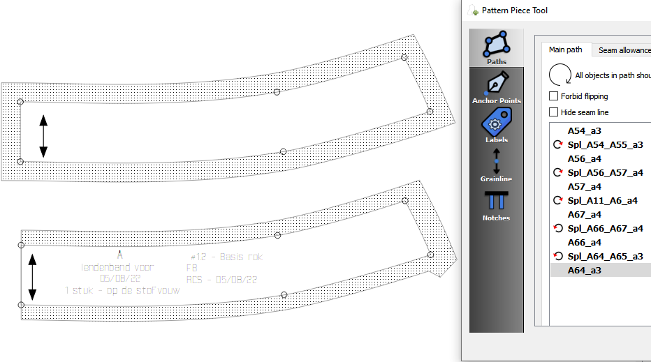
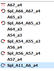
I’m getting 2 weird corners this evening. The rest is just fine.
patterntest.val (90,7 KB)
measurements.vit (669 Bytes)
I would check the direction of your curves or of if you missed any points or curves. I just added this piece and just set a default seam allowance. It’s fine.
It starts as soon as you change some seamallowance to 1,5 cm. Also weird things happen if you change the starting point. (not changing the order of points, just starting at the “weird point” does this.
Suddenly you get this shape in part B.
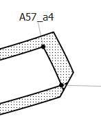
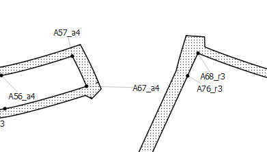
And if you do the same in part C, you get this:
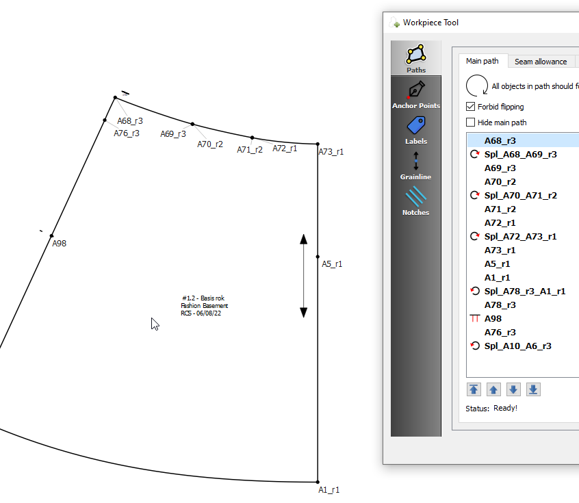 the seamallowance is reduced to one little piece, that contains al the labels and grainline info. The notch (on point A98) stays visible.
Is it because they are curves? (I checked the direction) These are curves that have been moved, but not with their original endpoints, just with two points on the curve somewhere halfway.
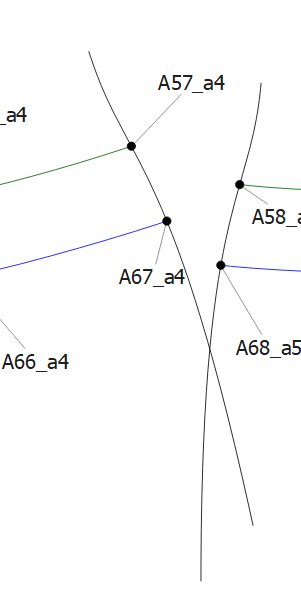
I have done this on other points, and they are just fine.
Also, the miter angles don’t seem to do anything on the corners in the entire project. not even on the “test” square
Hmmm… yeah, there seems to be something odd going on with the SA on the moved curve section. When I have the time I will need to investigate futher to try and pinpoint or as the case maybe - reproduce - the abnormal behavior. Varying the SA on those 2 nodes or changing the starting node of the path produces some odd results at that one node.