That’s a loaded question… but I’ll try to break it down to just the basic idea with 1 curve using interactive control points. Note that Seamly2D uses bezier curves… which we’ve defined as:
- Curve - interactive
- Curve - fixed
- Spline - interactiive
- Spline - Fixed
where a “spline” is nothing more than consecutive curves, with the control points between curves automatically set 180 degs apart so as to provide a smooth transition from 1 curve into another.
The other factor that determines how smooth a curve flows is the length of the control points. Not only is this important in just drafting a single pattern, it’s essential to change the length of the control points with the measurements. That’s where you will see users defining the length of the control point by some formula of length * a factor. It’s easier to look at curves within a triangle… with the control points along each leg and the curve along the hypotenuse… like:
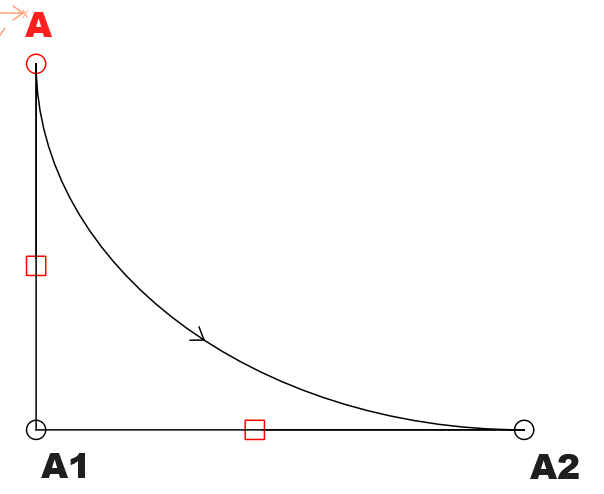
Where the length of the the control point at A = the length of Line_A_A1 * factor and the length of the control point at A2 = Line_A1_A2 * factor.
So just what is the value of the factor? Well without getting into the math it’s an approx for bezier curves and can be defined as 0.551915. So in other words the length of control point A = Line_A_A1 * 0.551915… so basically 55% or a little over 1/2 the length. So again, what this accomplishes is a smooth transition for whatever is before and after this curve, and regardless of the “size” it will always be proportional.
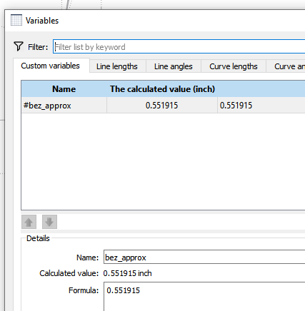
Something that I do is put the bezier factor into a variable in the “variables table” so it makes it clearer WHAT the factor is for.
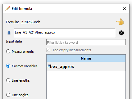
So now the formulas become:
You may then be wondering well how would all this apply if you need to find those triangle leg lengths. if they not given? Well then you have to add points to allow you to have access to the line lengths as illustrated here:
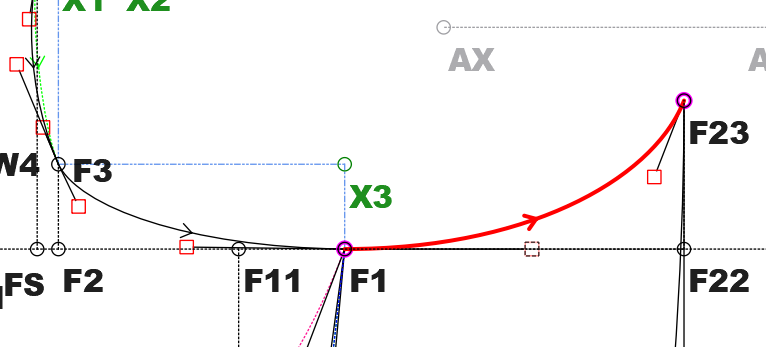
Here you can see I needed a lengths for the curve between F3 and F1… so I added the point X3. Now I have access to Line_F3_X3 and Line_F1_X3 and the control point lengths become Line_F3_X3 * #bez_approx and Line_F1_X3 * #bez_approx. BTW… I could have just added lines F3 - F2 and F1 - F2… but I find it gets messy with over lapping lines.
Just another note… as you will run into this issue at some point - you need to define any lines you need BEFORE creating the curve as you can only access tools that have created BEFORE the current tool.
Hope this helps.