Sorry me again I would love to have the option to draw a paradelle in draft modus. It would be really helpful for facings. for example neckline or just upper collar. Partially I can solve the problem in piece mode to add for the upper collar 3mm seam allowance. it gets difficult for facing at hoods. Solved in Illustrator right now.
Also difficult for hems. Or i am to stupid to use the option of “custom seam allows”. Is there a somewhere a instruction?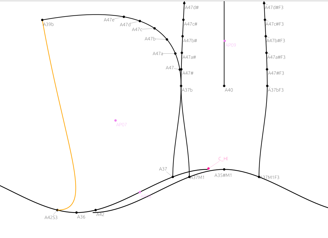
2 Likes
If I understand you correctly, you seem to have a pretty good handle on how to get it done. You could, of course, insert all the elements to construct a parallell curve, but using a false narrow seam allowance is the easiest. A similar question came up a few years back, but I don’t remember exactly.
Custom Seam Allowance will not help you here, it needs objects to build on & is usually more trouble than just using an odd width on your seam allowance.
I hope that helps a little, but it’s past my bed-time.
![]()
1 Like
Yeah… the custom seam allowance is more for when you want to do something like a fold down hem on a sleeve… but without having to draft it in draft mode like I did below:
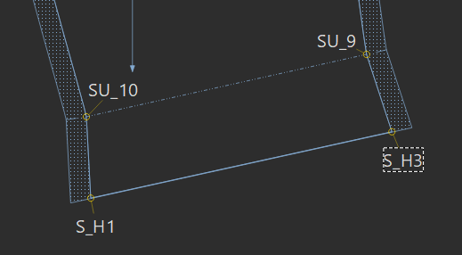
With the custom seam allowance you can create say a 2" hem along SU_10 to SU_9 without the points S_SH1 and S_H3. You do need to create those points above SU_10 and SU_9… where you define the custom seam allowance as the parallellagram above the hem line, and it gets added onto the rest of the piece’s seam allowance path.
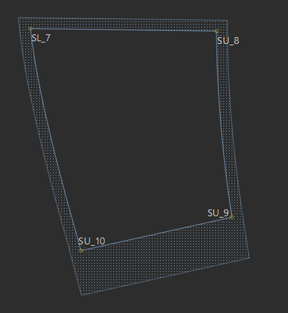
This is what we don’t want… if we just add a 2" hem.
2 Likes
I would like to have such an option as well. Working with M&S instructions they often draw a base model and the move lines parallel up/down, left/right. It would be nice have a simple option avoiding to create different points and lines manually. Or I am doing things wrong and we have already something to use?
I read in the forum (post from far in the past) for the difficulties with curved lines. But since we have already the seamallowance working wuite good, I guess it’s technically feasable
1 Like
I totally agree, but I can’t picture in my head how this would be obtained. What I’ve been doing all the years, where curves are concerned is that I actually create a curve and then copy the formula’s over (by referencing the curve handle’s length and angle) to the new curve. This is especially useful when drafting an underwire bra.
Anyway, I’m sure the developers are thinking about how to implement it.
What I like about the Move and Rotate tool is that if you change something in the original, it automatically changes in the duplicate.
1 Like
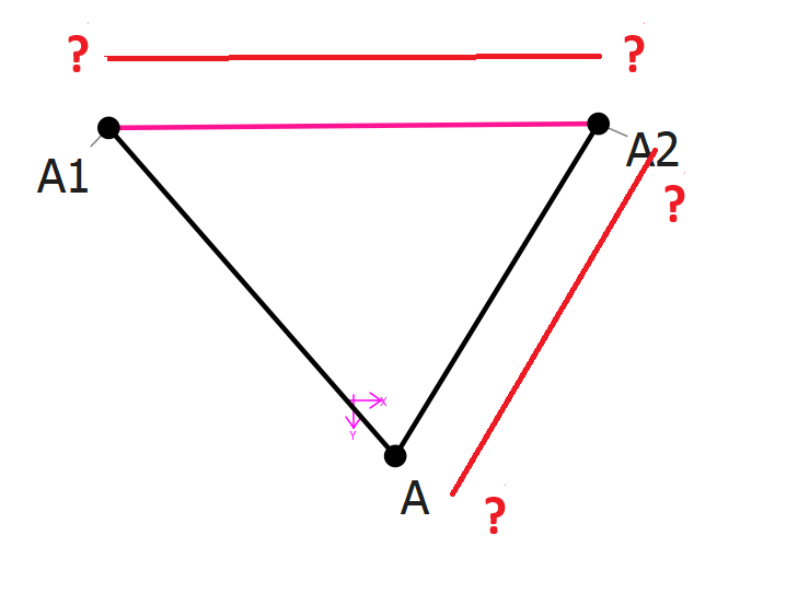
Not the same thing. The SA is based on a fixed main path, where the cutline is an path outside the mainpath created by extending the corner points. The Citline node points only have meaning for the SA. That’s not the case in draft mode. For example lets take the simplest case - a line between 2 points A1 and A2. So how do we draw a parallel line? Where do the second set of points come from? Lets complicate it… lets draw another line from A2 to A… where do those points come from, and how do we connect the 2 parallel lines?
Getting even deeper into the weeds… how do we draw a new tool from one of the parallel lines?
Not really. More like thinking of all the issues that would have to be resolved to even make it work. IMO… one drafts a second set of points using existing tools - maybe using the move tool - to create a parallel.
2 Likes
I think we can mimic the behavior of CAD softwares. It could be an “offset” tool more than a “parallel” tool (that could be used with splines too in a second time). For lines:
- if a single line is selected, it creates the end points of the parallel line so that A2 A1 A1’ and A1 A2 A2’ form right angles.
- if multiple lines are selected, it takes the intersection points of the offset lines, and if the selection is not a closed loop is sets the end points as described in the first case.
I’m talking about lines to simplify the thing, but I think that the selection of the path to offset should be the same as the one from the piece tool: we should select points and splines between them in a particular order.
But I agree that this would be a HUGE amount of work to program this. I also agree that offsetting a spline or a line is one of the feature I miss the most in Seamly ![]()
2 Likes
A line doesn’t create points. That was one of my points.
In my example there is Point A1, and Point A2… there is Line_A1_A2… there are no points A1’ and A2’ to create a parallel line
You can do it… it just takes a little more work. ![]()
But, again… my second point… how do you create a tool that actually creates an A2’ point out where point A3 is so that 1) You can then create a parallel of Line_A_A2 that connects with Line_A1’_A2’ 2) Have the A2’ point actually where the 2 lines would intersect (A3) is so THAT point can then be further used such as point A4. You have no way to predict where point A2’ should be… until you add Line_A1_A2’'. Referring back to comparing it to the Seam Allowance… the seam allowance is fixed… we know the main path, which we can extend out to create another cut path. We can’t do that here, and unless you can connect parallel lines to other parallel lines, it’s rather useless.
That’s HUGE just to solve this for a Line… then add all the curve tools.
1 Like
And my point is that this offset tool should create points and not lines ![]() The points A1’ and A2’ would be created by this offset tool
The points A1’ and A2’ would be created by this offset tool
1 Like
I don’t think I’m understanding the problem you’re explaining.
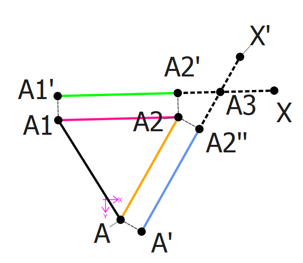
In the case you mentioned:
- the user selects, in order, A1 A2 then A.
- a popup asks for an offset x
- we compute A1’ so that A1’ A1 A2 is a right angle and A1 A1’ is x
- we compute A2’ the same way
- we compute A2’’ and A’ the same way
- we compute A3 as the intersection of the two previously computed parallel lines.
- the tool only creates the points A1’, A3 and A’.
- the tool could create the lines between those 3 points…
It’s quite a lot of work but I don’t see the problem you points out
1 Like
From where? And if so then what? Like I said you can’t continuously connect those points to anything. Which in the end you would only have to do what I did above. And if all you wanted to do is create points A1’ and A2’… just use the move tool. It’s already there.
Like A1_a1 and A_a1:
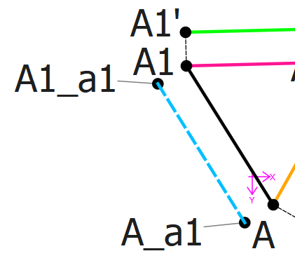
1 Like
That’s because offsetting a single line is not useful, but it gets more useful for connected lines like the example given in my previous message.
1 Like
In this case the offset tool would create A1’ A3 and A’, that can be continuously connected without having to create all the temporary points.
And again, this is relatively easy to compute for lines, but it would be far more interresting to have this tool work for splines…
2 Likes
I am working also with VStitcher there is an option of offset path extend to edges. Saves a lot of work.
Just a stupid idea to solve the problem.
An offset path, seam allowance, works really well in piece mode even for curves. Maybe it would be possible to simulate a “fake pattern piece” in draft mode.
My idea is
Adding a tool for offset path.
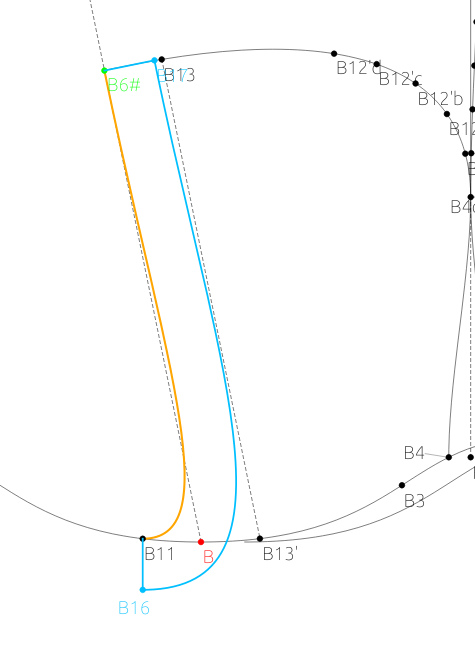 Offset tool would work like this
mark the area (a closed piece): B11, Spl, B6#, Spl, B4 Spl “Fake pattern piece”
mark the line: Spl_B11_B6#
offset: value -35mm of -#width hood facing
Could this be a viable solution?
Gr
Michael
Offset tool would work like this
mark the area (a closed piece): B11, Spl, B6#, Spl, B4 Spl “Fake pattern piece”
mark the line: Spl_B11_B6#
offset: value -35mm of -#width hood facing
Could this be a viable solution?
Gr
Michael
2 Likes
Hi Douglas, I’m on holisays right now, but when back home I’ll describe it more detailed. What I was thinking about was having the possibilty to add some offset when using existing tools. So when creating points where lines/curves cross it would be handy to set an offset of those lines/curves.
More later on. And thank you for your very detailed answer. Helped me a lot
1 Like