Here is a part of a tutorial I’m busy writing based on the tutorial that I posted in the topic Super Easy Way to do the Armhole Curves:
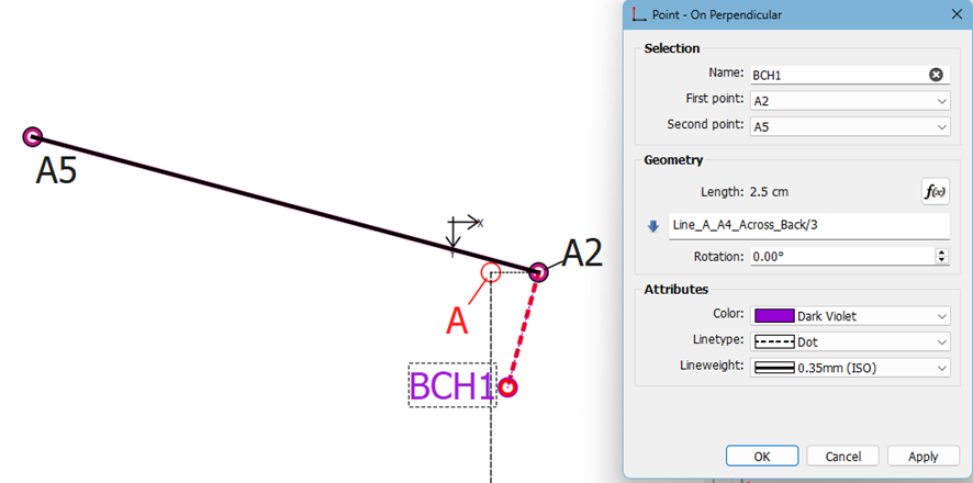
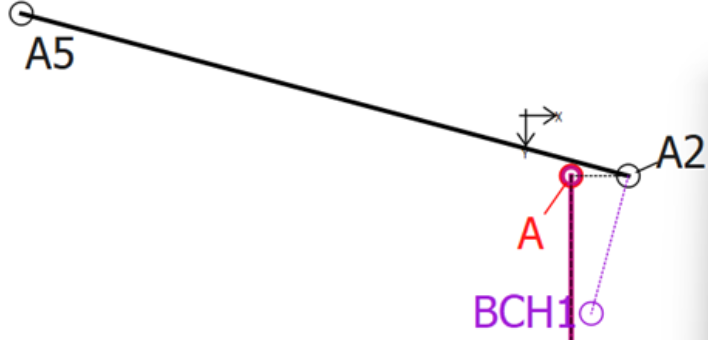
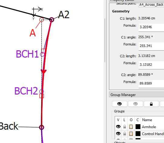
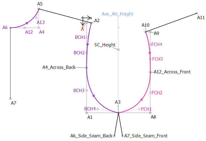
BHC1 - In my example, I have used the Point – on Perpendicular tool and click on the shoulder tip point A2 and then on the neck side point A5 to create a point at 90° to the back shoulder line. The formula entered for the length is Line_A_A4_Across_Back/3. No other setting needs to be adjusted.
My reason for using this formula is that I would like an even curve stepping inwards a distance and downwards a distance, but since the distances involved won’t form a circle, but rather a portion of an ellipse, it is divided by 3 instead of by 2 which would happen if I was creating a portion of a circle.
If the curve handle should protrude into the fabric of the back bodice too much, I would divide the longest line by 3.5 or 4 (or more), instead of 3. This applies to all of the curve handles as they are easily adjustable, individually, to create the most pleasing curve.
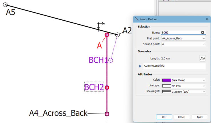
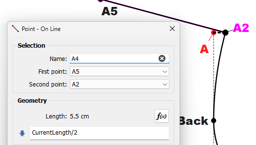
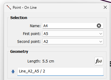
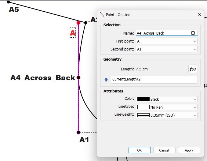
BHC2 – Here, I’ve used the Point – On Line tool and the length formula CurrentLength/3. This is actually the same formula as in the previous tool and I could have use the formula Line_A2_BCH1 but I may wish to change the formula, so I’d rather keep the two formulas totally independent of each other.
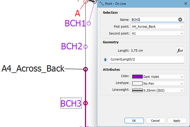
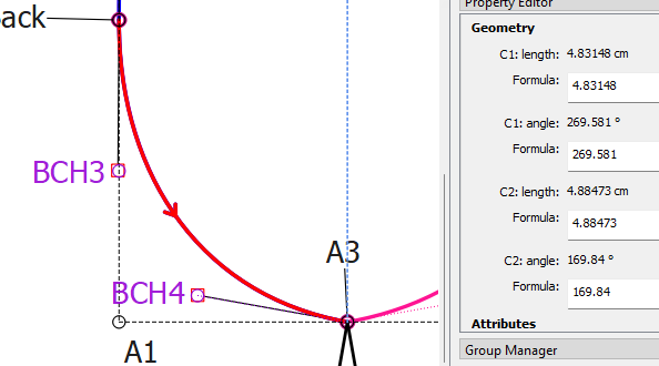
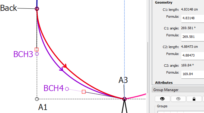
BHC3 – Again, I’ve used the Point – On Line tool but the length formula CurrentLength/2 because this is more a portion of a circle than an ellipse.
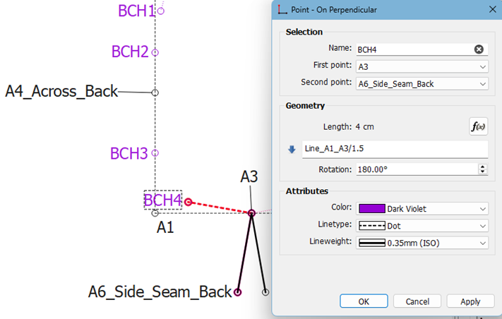
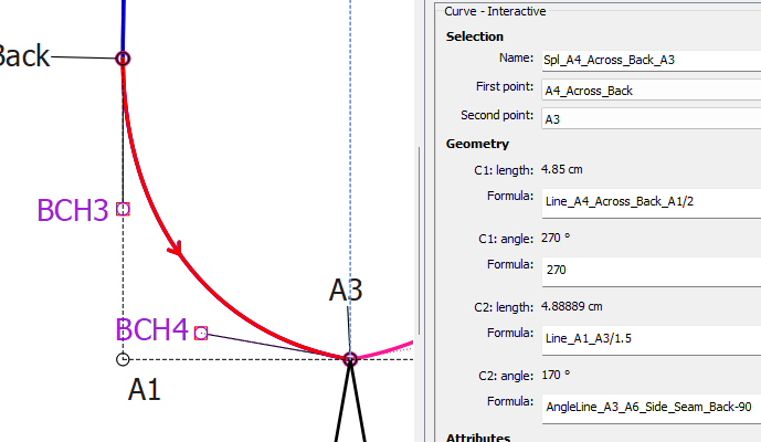
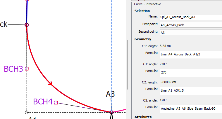
BHC4 - I have used the Point – on Perpendicular tool and clicked on the armpit point A3 and then on the back seam side point A6_Side_Seam_Back to create a point at 90° to the back side seam line. The formula entered for the length is Line_A1_A3/1.5 because I would like a slightly deeper circle portion. Change the Rotation to 180° to place the point correctly.
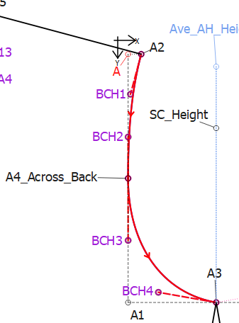
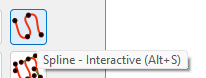
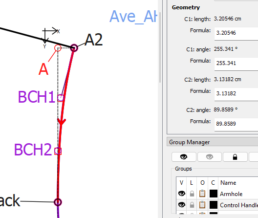
Back Curve = Pick up the Spline – Fixed tool and click on points A2, BCH1, BCH2, A4_Across_Back (section 1), BCH3, BCH4, A3 (section 2). Hit Enter.