Getting Used to the Spline Tool **LONG POST**

As the title says, I’ve been working on getting the hang of the Spline tool. While I’ve made some improvements, I’m still not getting the results I want, and, more importantly, I don’t feel in control of the tool. It’s more like I’m a bull rider just trying to stay on and keep the bull between me and the ground.

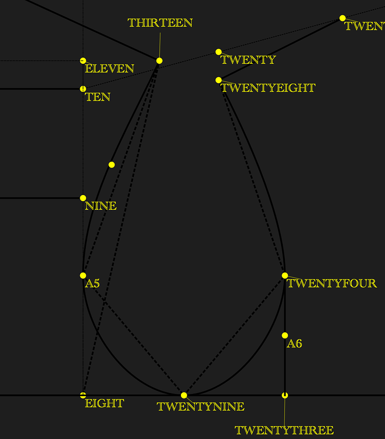
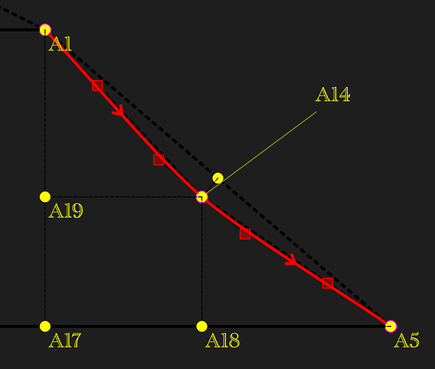
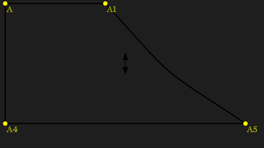
In the first attached image, you can see a screenshot of the spline. (It’s from a test file I made, not part of an actual garment, in case you were wondering.)

There are three nodes in total, with four control points.

Here’s how I’ve been trying to create a decent spline curve:

Control Point 1
The length of the first control point (at A1) is one-third the distance between points A1 and A14. This is pretty arbitrary, but it matches what I’ve seen in tutorials. I’d love to know why this is so common (or how to figure out when to divide by more or less). The angle of this control point matches the angle of the line A1_A14. My reasoning is that when I deviate from this angle the line gets a weird bulge between the first and second control points, which doesn’t look great, at least for a symmetric curve.

Are there cases where this bulge is desirable?

Control Points 2 & 3
The lengths of the two middle control points (around A14) are set to the length of A1 to A5 divided by eight. This is, again, totally arbitrary not just the division by eight, but also using the measurement A1_A5 in the first place. Honestly, I’m not even sure my reasoning holds up. Having them the same length does seem logical for a symmetric curve, but I wouldn’t know what to do for a non-symmetric one.

Are there situations where you wouldn’t want the middle control points of a spline to be the same length?

For symmetry, I’ve also made their angles match the angle of the line A1_A5, which kind of makes sense to me. At point A14 (or any middle point), I figure you’d want the curve to flatten out a bit, right?

Control Point 4
I tried to copy what I did for Control Point 1 here since it felt like the logical thing to do as I wanted symmetry in the curve, but now I’m questioning that because it didn’t give me great results. Though I’m unsure if it’s my execution or simply the fact that the control points shouldn’t have been symmetrical. Like Control Point 1, the length here is the distance between A14 and its node (in this case A15_A5) divided by three. The angle is the same as said line, minus 180 degrees.

Am I close or do I have a fundamental misunderstanding of how to define curves (using the Spline tool) as a function of their points’ attributes (e.g. using the length between the points that make up the curve as a basis for the length of control points)?
1 Like

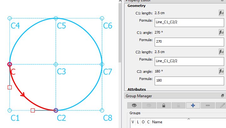
If you wish to make a perfect circle, then you’d divide it by 2, but if you would like a more oval effect, then you’d divide it by more. I always start with 3 & if I don’t like it, then 3.5 or 4, sometimes even as much as 8. The important thing is to start with an existing line in the pattern that will resize when you change the measurements.

Yes, that’s a straight line between the 2 nodes, so your curve will be pretty much a straight line, as well. I’d minus off 10° or so to get a neat curve in my test piece, but I’d find a different line to use as the angle in my pattern - a line that is connecting to the curve.

For instance… here I’ve used the shoulder seam line and added 90° to give the 1st control handle an angle at 90°. This way, when I sew the shoulder seams of the garment, the back armhole will form a straight join with the front armhole.

In this case, I’ve used the line connecting to the curve as the angle of the control handle:

This is the back crotch curve. The 1st control handle is used as the angle of the connecting inseam curve, so I normally start at 0° and add on 10 or 15° until I think I like it and that it will treat the inseam nicely, too, (or I base it on the front crotch curve connecting curve handle).

At the center point, I base it on the angle of the line + or - 90°:

The lines between the points determine the length of the curve handles, which I start at /3.

If you look around your pattern there will always be something in the construction that will guide you with the angles and the connecting lines between the points will give you lengths to work with.

You’re pretty close, the only thing that you’re missing is what comes before & after the curves. Working with just a few points isn’t an ideal way to picture the curves. Ask yourself what is it going to look like when you sew up the garment? Are the seams going to peak out at the seam? Or is it going to peak inwards?

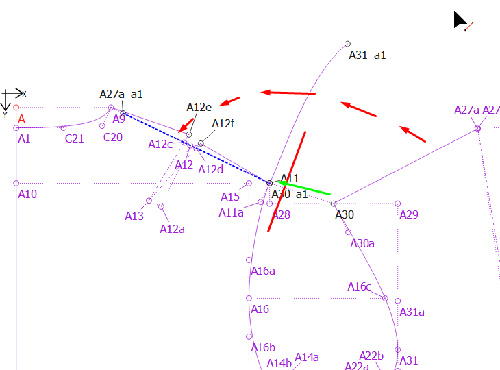
Here, I’ve moved & rotated the front shoulder seam and part of the armhole curve over the back shoulder seam so that I can check what it will look like once I’ve sewn the shoulder seams together:

image

I hope this makes things slightly clearer. The only thing that really helps is to do the moves & rotations to check things and then to sew up the garment. Only then can you really see if what you’ve done is working or if it needs tweaking.

2 Likes

Looking at this, a lot of things are starting to make sense like the need to define the first and last points as functions of what comes before or after them to ensure a smooth transition. (That was something I’d completely missed before.) So thank you so much for that! I do have just three quick questions:

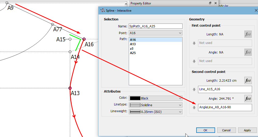
  1. In Image 1, you use the line A15_A16 as the basis for the length of A16’s control point. Was A15 already a point on your garment, or was it just the intersection between A13 and A16? Either way, what’s the reasoning behind using (and/or creating) that measurement as the basis for the length of the control point?

  2. In Image 3 (which covers the second node of the spline), you use the angle between D16 and D16a as the basis for the angle of the control points. While I can see that it works, I’m struggling to understand why it works especially when you add 90 degrees to it. I also don’t have much context about what points D16 and D16a are, which might be why I’m confused. For example, if D16a was created using the “point on bisector” tool on points D24 and D17, then adding 90 degrees to the angle of the line between D16 and D16a to would result in a line perpendicular to said line which itself is perpendicular to the line between D24 and D17. In layman’s terms, this would just create a straight line between D24 and D17, which would make sense to me but I’m not sure if that’s the case here.

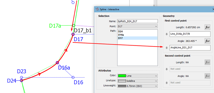
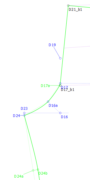
  3. In Image 2, the control point’s angle is the angle of the line D21_D17. Am I right in assuming that D21 is the next point just above D17, slightly off-screen? That would make sense given how important it is for the spline’s start and end to reflect the curves and lines before and after it to ensure smooth transitions (I think that is why it’s so important but maybe I’m mistaken).

1 Like

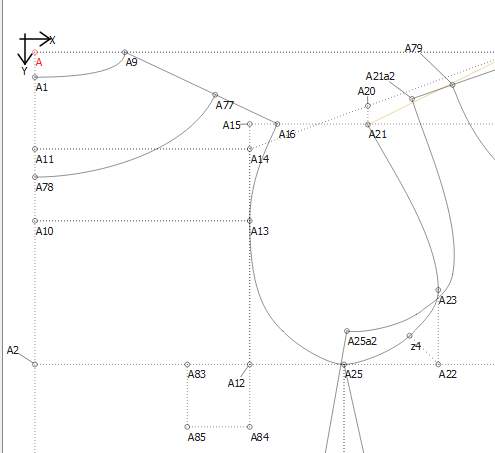
Ok, yes, it is an existing point in my pattern. It’s the intersection between the shoulder tip level and the half across back measurement which defines the side of the back armscye.

image

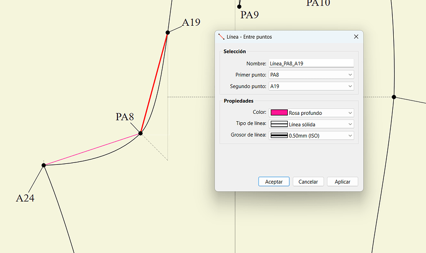
This is a pattern that I made in about 2018, so I was still learning. I didn’t want the curve to go beyond the line A12 to A15, so I anchored it by using the line A15_A16.

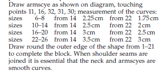
Ok, Aldrich books normally specify that you need to touch the curve on a point that is x distance from D16, according to size.

image

So that is where this line comes from. The reason that it’s at 90° to this line, is so that you don’t get a jag in the smoothness of the curve when it comes to this point.

If you don’t have this in your pattern, skip it. and only use the angles and lines that you do have.

Yip! Sorry about that. It’s the centre back seam on the trousers. The crotch curve needs to transition smoothly into that seam line.

image

You may take notice of the points D24a & D24b where I’ve also used the angle of the line +/- 90° for the angles but I’ve used the lines between the sections as a base for the lengths of the curve handles, because the curve needs to travel longer distances.

Edit: Sorry, I gave you the armscye points to touch in the curve instead of the crotch curve:

image

1 Like

With everything you’ve shown me, I just created my first armhole curve completely on my own, using only the lines I already had and without following anyone else’s instructions. Thank you so much!

2 Likes

LOL, you’re very welcome, How about an image?

Just remember that everything improves with practise. I can only give you guidelines as to how I do it. You will probably develop your own way of doing things.

1 Like

It’s nothing incredible but here you go. When I copied others’ instructions it would work but I didn’t understand why, now it works and I can make little changes and justify every decision I made.

I was working my way through the Aldrich book and then got stuck on more complicated curves. Now I can finally progress I feel

I also made this little checklist to go through, it’s not perfect I don’t think so I don’t take it as gospel but it’s just a guideline

2 Likes

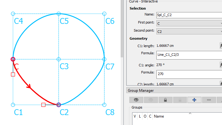
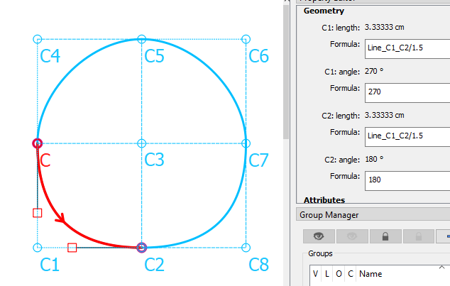
Your checklist sounds good to me, as long as you understand it. The only thing that I’d clarify in it is that a half length makes a perfect circle and a very short length will make a corner, so the shorter the length, the more square it will be?, if that makes sense? The longer the length, the more gentle the curve.

Here is a circle. All squares are the same size and all handles are the same length:

image

Here, the bottom half of the circle, I’ve divided the length by 3, so the curve is a lot straighter - or gentler:

image

And here I’ve lengthened the handles - multiply by 1.5:

image

These are just so that you can compare the effects of the longer & shorter handle lengths.

3 Likes