I seem to be having a problem with understanding the mechanics and processes in the use of interactive splines and the control elements thereof.
I thought I had got this down pat, but it would seem not to be as I thought.
Here is my issue:
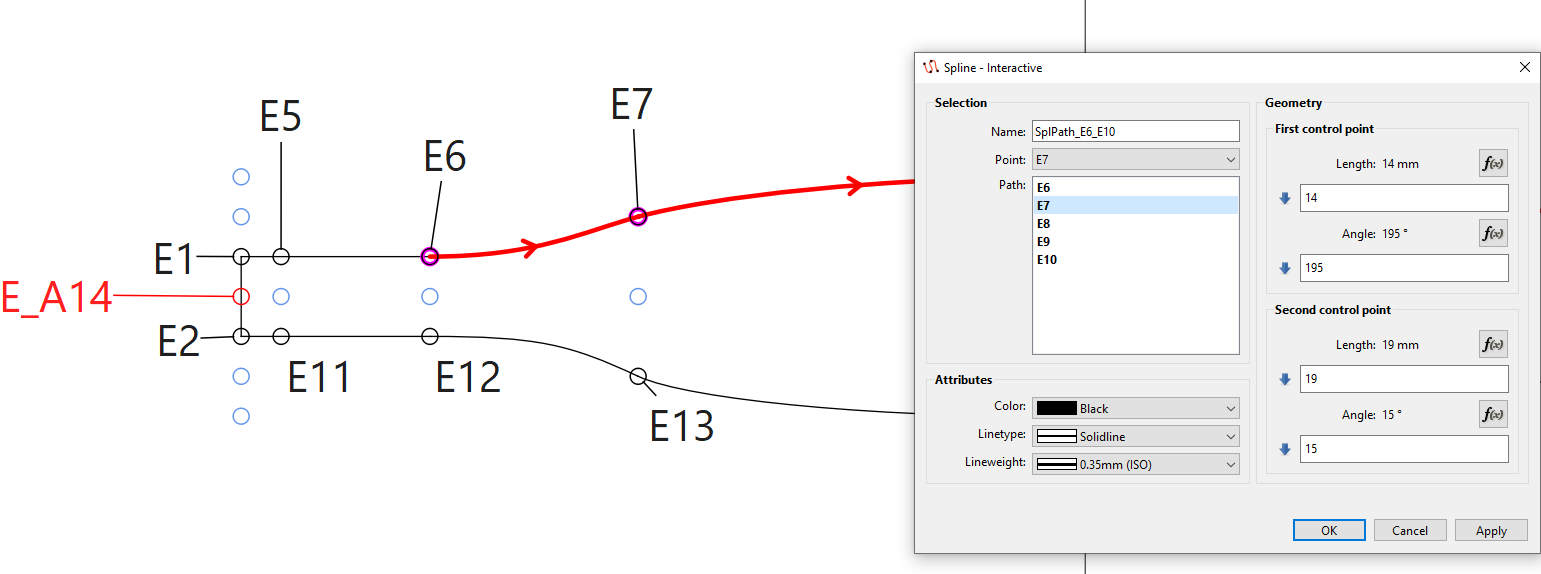
I have a ‘Piece’ drawn using interactive splines, whereby the top (E6 → E10) and bottom (E11 →
E16) splines should mirror each other. I do realise that I could just mirror the top to bottom to obtain the desired symmetry, but I wish to be able to use the control elements correctly and not just get results by ‘Hit & Miss’
So basically I would like to be able to transpose the control element Lengths (easy) and Angles (Hard for me apparently!) from the top spline control points (in this case) to the bottom one, therefore ensuring complete symmetry.
I have probably made this too difficult for myself and tied my brain into pretzels! So any assist in untying this knot / finding an elegant solution, would be gratefully received.
Greetz from Sunny Germany,
David D.
PS: I have only supplied the data for the opposing elements ‘E7’ & ‘E13’, which may coincidentally correct, but this would be more luck than applied knowledge!
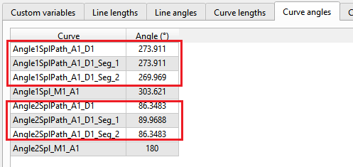
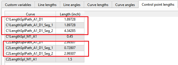
You can access the Curve Angles of a spline (which represent the Control Point angles), and the Control Point Lengths for use in the formulas. Of course you can only reference a spline that was created before the one you want to apply the CP angles and lengths to.
When you want to ‘flip’ the curve, find a reference point on the 1st one and think how this angle compares to the reference line.
My ideal reference line would be 0 to 180°.
Therefore, E7 is 0+195° on the 1st curve handle’s angle, which = 195° (180°+15°)..
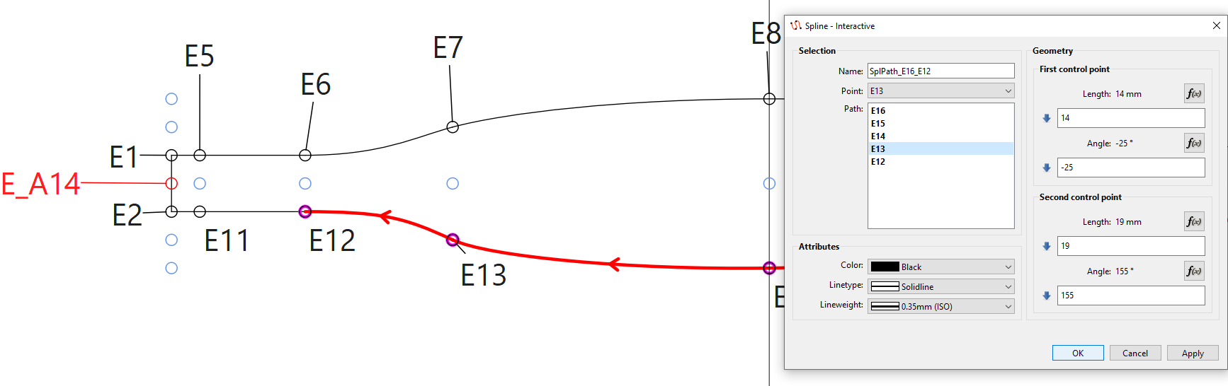
On E13, you have the curve going clockwise so the 2nd curve handle mirrors the 1st on in E7, so the formula will be 0-195°, which will = 165° (180° - 15°).
On E7, the 2nd handle is 195°-180° and on E13, the 1st handle is 165°+180°.
If you are going to use this pattern over different sizes (measurements), then it would be better to reference the E7 angles in the formulas at E13 (see @Douglas reply) instead of using direct measurements, however that is up to you.
The lengths at E13 are identical to the lengths at E7, just baring in mind that the 1st control handle in E7 is mirrored by the 2nd control handle at E13.
Thanks for both of you for your responses which have helped in my (minimal) understanding of the subject.
However, I am aware of where to find the details of the properties of the spline controls, but was and am having issues of applying some sort of ‘rule’ or ‘formula’ for transposing the control point angles (of the original) to a duplicate (mirrored or rotated) of said original.
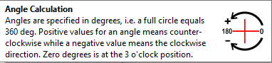
I think, on reflection, that the help text shown when hovering over the CP-Angle textbox may have made my confusion worse initially (rotation direction and degree).
BTW: this issue has been clarified by your explanations - Thanks !
Perhaps of some simple, easily understandable explanation / example, might assist me here
Part of this query applies to my ‘real world’ application and part is get the knowledge and ability to apply the logic to any situation regarding the use of vector controls in this application.
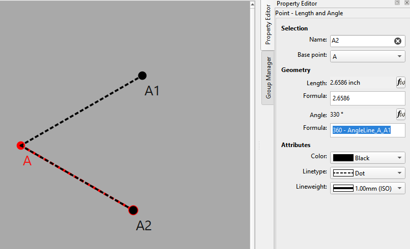
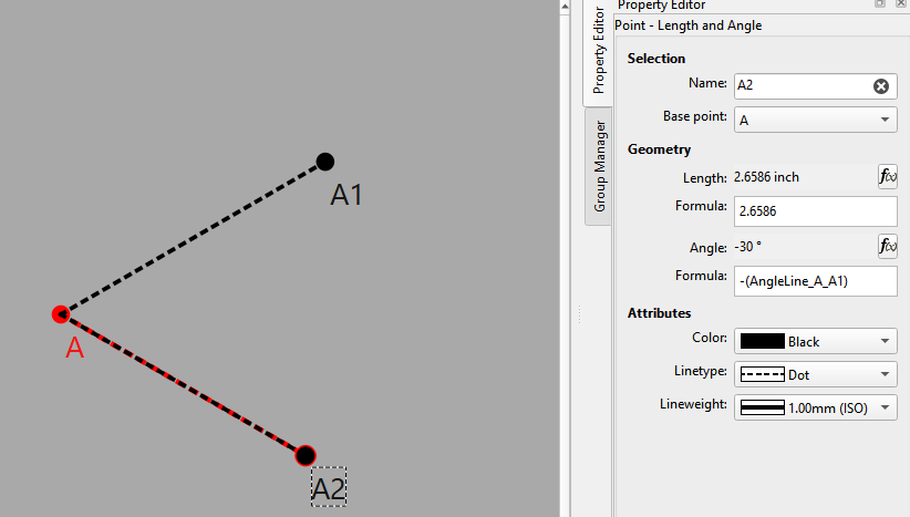
I should probably have added to what I previously showed was mirroring vertically… and if you mirror horizontallly then you need to 'flip" the angle 180degs… if we take the same 30 deg angle line… it’s 360 - 30 -180 = 150 OR 180 - 30 = 150 OR 0 - 30 -180 = -210 OR -(30 + 180) = -210.
You just always have to think of the angle of the line is in relation to the point at which you are revolving around starting at 0 (360), and whether you’re going CW or CCW. For me I prefer to use CCW and plus value angles.
 BTW: this issue has been clarified by your explanations - Thanks