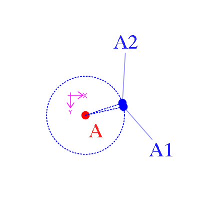
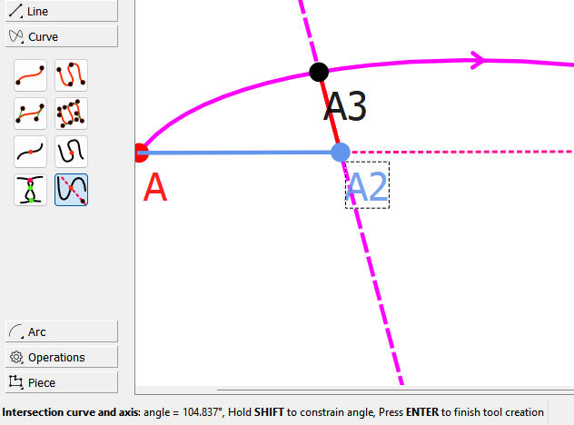
Is there a way to lock in on a point more precisely when using Intersect Curve and Axis tool? (And probably more tools as well). On the next example you see what I mean. The A2 point was created while the A1 point indicated (by growing/highlighting a bit) that I had hit it. Ofcourse I could zoom in a lot and that would make it more accurate . But a lock-in/snap wouldn’t go amiss, if it isn’t already there. Deviations can add up over distance. The radius of the arc is 2cm, I used 100% as ratio. I had expected it to be more precise.
1 Like
Pardon my ignorance, but why are you wanting to put a point where there already is one?
![]()
1 Like
Exactly my question, too ![]()
The problem here is that the A1 node has taken a certain amount of space to show its location, so A2 has crammed itself as close as possible to the location it is set at, without dislocating A1. With that said, I have never needed 2 nodes in the same place. It’s much easier, neater and accurate to use the point A1 a multitude of times if the 2 points are to remain static over various sizes. Should 1 of the 2 nodes move according to size changes, while the other remains in place, then it makes more sense to me and the one that moves will move to the correct position without the node displacement.
(@Pneumarian, I guess I’m time travelling again ![]() )
)
Because I needed to, it was the easiest way (and simplified at that) to show what I had encountered in an actual pattern. A line going through an already existing point, hitting a curve. Perhaps the following is better to understand.
A-A1-A2 and the splice between A1A2. Now create the node on the splice for a line crossing the splice from A to B. Both R1 and R2 seem valid solutions as during creation of both nodes the B node indicated I had hit it. But there’s nearly a 3-degrees difference between them. It is the intersect curve and axis tool that does this, the Length and Angle tool does snap to the target. (but, ofcourse, doesn’t create the node on the splice)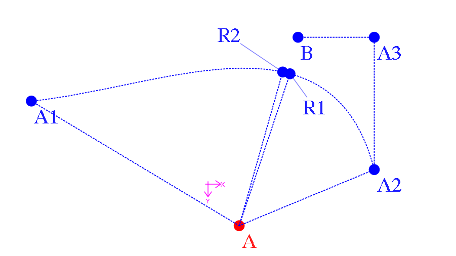
2 Likes
But why the 2 points? I have no clue what you’re trying to do?
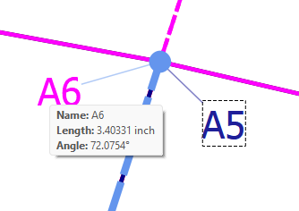
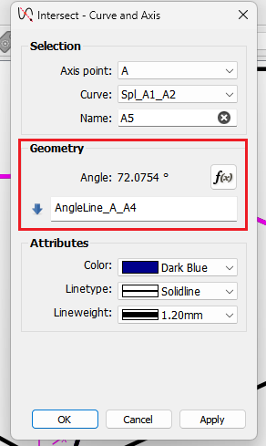
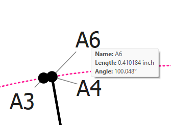
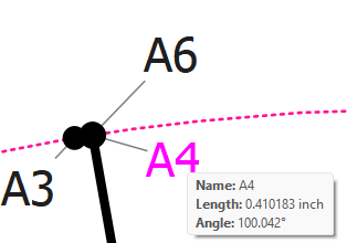
I did the same sort of thing,… Created Line_A_A1 and Line_A_A2 using Point - Length and Angle. Created Spl_A1_A2. Created Line_A_A4… then using the Intersect - Curve and Axis created points A5 and A6 using the angle of AngleLine_A_A4.
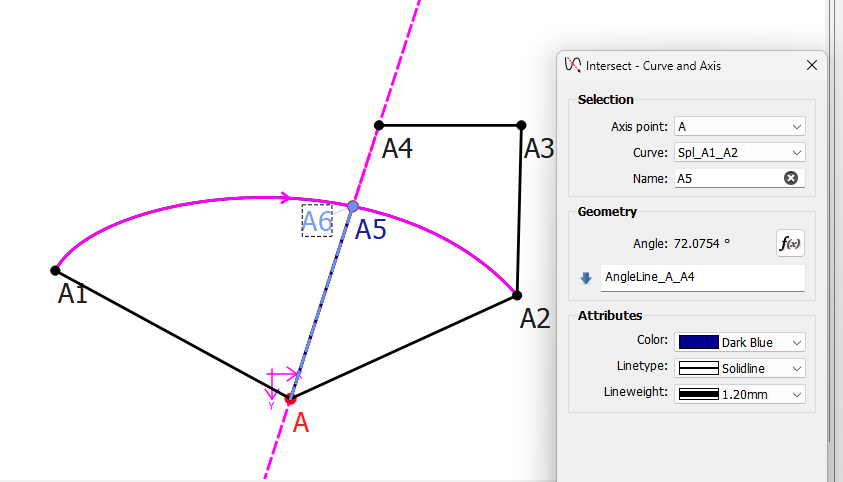
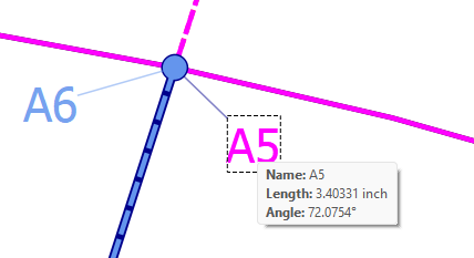
Points A5 and A6 are EXACTLY the same.
The Point - length and Angle tool doesn’t snap to anything… it does as the name implies… it creates a point at a given length and angle.as per the length and angle formulas
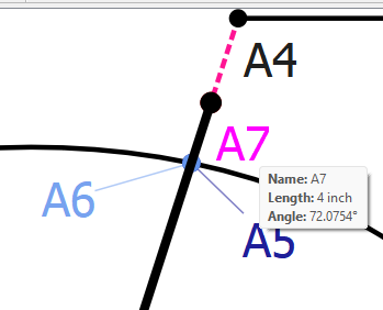
Drawing Point A7 using Point - Length and Angle with the same AngleLine_A_A4… Line_A_A7 lies EXACTLY on the same point as A5 and A6… it has to.
1 Like
Yes. Use the angle formula.
There is no “snapping” in Seamly2D… other than using the Shift key to constrain the angle by the 45 deg angle steps for the Intersect - Curve and Axis tool.
![]()
The interactive visualization is only there to get you in the ball park… you need to refine the formulas if you want accuracy.
2 Likes
- Use the Line tool (in the Line toolbox) to mark a line from A to B.
- Use the Point Intersect Curve & Axis tool with AngleLine_A_B as its angle.
Whenever you’re within selection range of a point, it highlights, regardless of whether it is actually selectable at the time. It’s not worth adding suppression code for every individual little instance where it isn’t actively helpful. We probably do need to make sure that it’s mentioned in the manual though.
ETA: That said, @Douglas would it be reasonable to make the Point Intersect Curve & Axis tool capable of using either a raw axis, (as is,) or a line segment, (as the Point Intersect Lines tool does)?
![]()
1 Like
It would be very inefficent to do so. Since each point is a seperate scene QGraphicsItem, to stop the points from acting on the mouse hover signal, we’d have to loop through each point item and disable the hover… the more points the bigger the loop. Then we’d have to loop through again to enable the hover for each point.
Again… I don’t see the reason for 2 points at the same place… or what the highlighting would have to do with swinging an axis? And if for some reason one does need to draw two axis at the same angle, you can always watch the angle displayed in the status bar…
You can certainly get it closer than 3 degrees. I just tried and got within .006 degs.
Also… without drawing a line between A and B… the pattern will not adjust properly if the angle is hard coded to what ever angle the visualization set in the angle formula… unless you want it set to a given angle like 45, 90, 180, 270, etc. Automatically adjusting IS the whole point of the application.
1 Like
There Is NO reason for two points on the same line. It is an example of what I noticed. Being able to create points that have a rather different in placement although the target point was quite the same. It looks that finally in the last post you understood what I failed to communicate. But OK it seems I’m asking unreasonable things. Thanks for your time, again.
1 Like
Sorry if I misunderstood what you were trying to do… I think we’re on the same page now.
Since we can’t get the angle between just any 2 arbritary points, we have to create a line between the 2 points using the Line tool, which then gives us the variable to use. In your second example that would be creating the Line_A_B. In the original you would have to create the Line_A_A1… which can then be used to create point A2 using the angle of Line_A_A1 in the formula of the Intersect - Curve and Axis.
Of course this would be 1 step easier if I could implement @Pneumarian 's Github new feat issue #409 Intersect Curve & Line, as the “Line” would be defined within the tool. It would also be a simpler tool as the only the the curve, and 2 points are needed - no formulas required.
3 Likes
This topic was automatically closed 3 days after the last reply. New replies are no longer allowed.