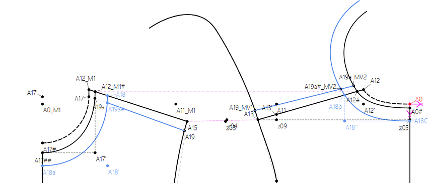
Hallo, as far as I know I can just mirror, move, etc the whole Spline. Just for a better work experience it would be helpful to operate with the segments. It gets really messy sometimes. No clue if it possible to improve it. @Douglas u know if could work
Not easy to do with the way the ops tools currently work. When you add objects to an ops tool the only information that is added is the object Id number. There’s no way to tell the ops tool what segments of a curve / spline you want to use.
Hello, @MG2024
I totally agree with you and have already discussed this with @Douglas
![]() with the same reply.
with the same reply.
My work-around is to make a simple spline, using the angle of the preceding spline (+180°) wherever possible, especially when I know I’m going to move/mirror/rotate only a segment, just to keep my work as tidy as possible. Unfortunately, this method is not always possible, but it does help.
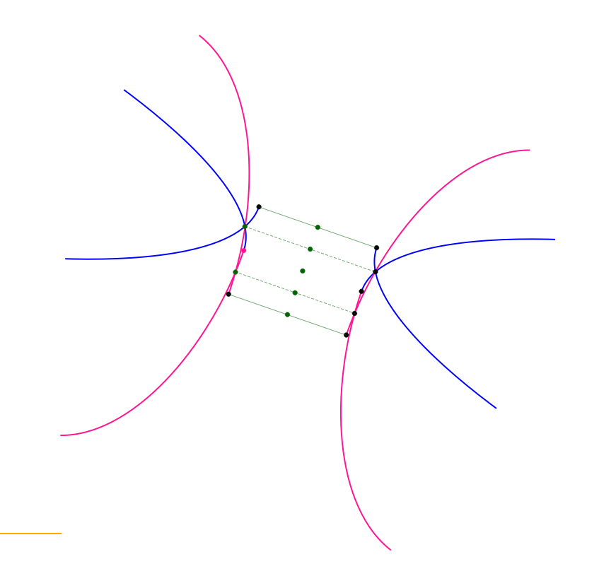
Ich kann Grace und MG2024 gut verstehen. Es ist immer wieder verwirrend, wenn man Teilabschnitte einer Kurve brauch aber die ganze Kurve spiegeln muss. Dann kommen solche Gebilde raus - ist mir heute wieder so gegangen
Solves the problem of “splines”, but not the issue of using a curve / arc / spline segmented by a “Point On” tool.
I don’t want to get in the weeds of how we get from the xml pattern to the data container to the graphic display… but the issue with either splines (which you can think of a curve with points IN the path) or curves / arcs / splines with point(s) ON the path that gives us the various segments - is that the “curve” is a single tool. 1 tool, 1 data Object, 1 graphic item. It’s why you can’t select “segments” of a curve - which would make more sense… such as creating a pattern piece where you might select seg1, point, seg2, point, seg3.
I’m not saying that there may not be a way to show / hide which segments we wish to see… it’s just not going to be a straight forward task. It’s complicated by the fact that ops tools and splines… like every other tool are dynamically created - as are the variables. So the spline or spline path names are created on the fly.
Hypothetical… we create a (simple) curve. Put a Point On the curve… so now we have 3 curve lengths. Then use the move tool with just the curve Spl_A_A1. but not the point A2
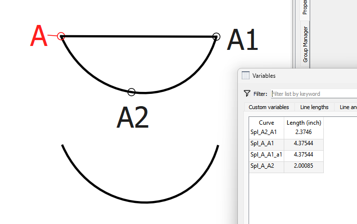
So then lets say we only wanted the Spl_A_A2 segment in the Move to show.
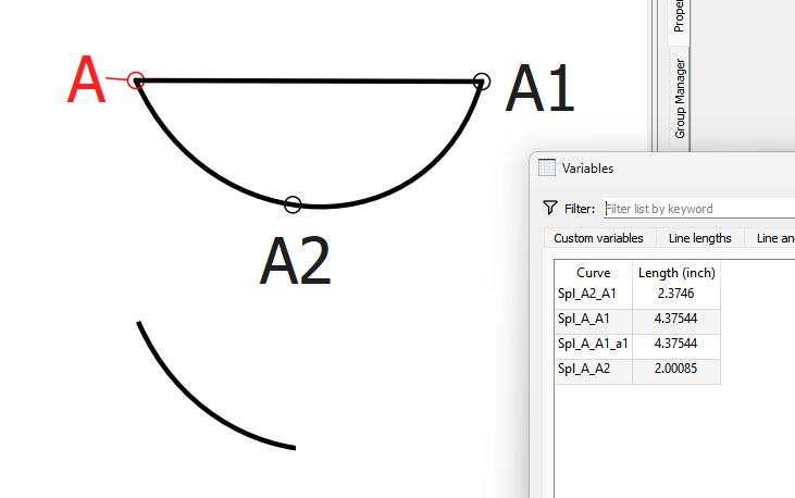
What happens if we delete point A2? There no longer is the segments Spl_A_A2 and Spl_A2_A1… so how is the Move tool supposed to display only the segment Spl_A_A2 when it no longer exists?
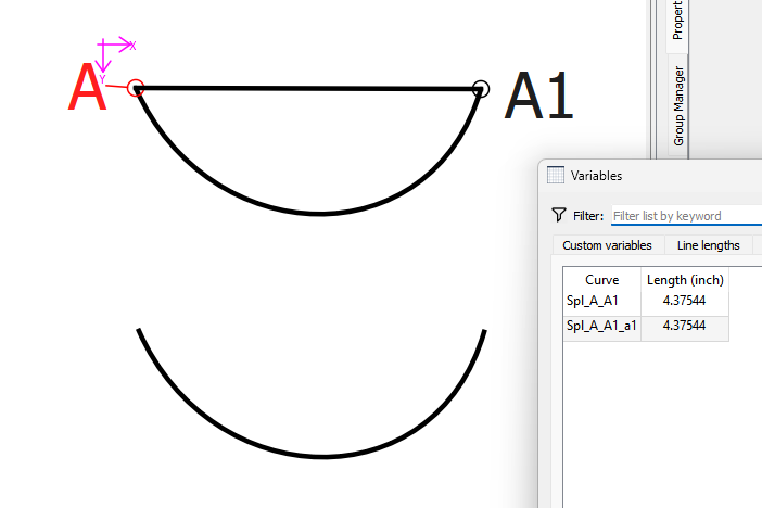
What really has to happen is the Point On tools need to is actually “cut” the curve / arc / spline into a point, and 2 new curve / arc / spline segments. So now you can select just the segment(s) you would want to opertate on.
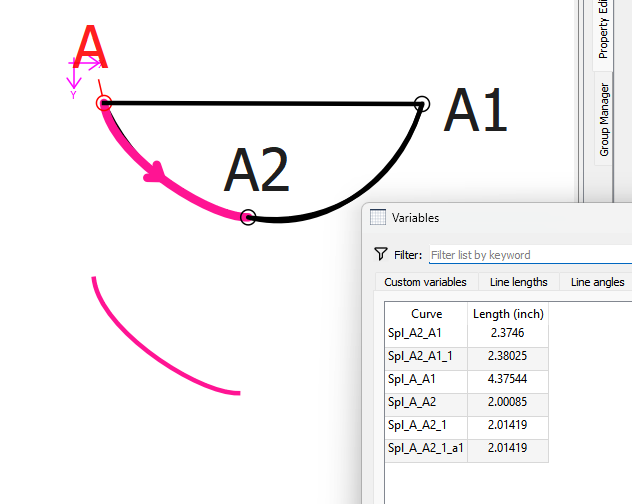
Of course the Point On tool is semantically different than Splines, the function is basically the same. The spline tools would need to be refactored to create multiple segments (graphic objects) rather than just 1, but then it would be doing exactly as @Grace has pointed out as her work around. That’s all splines are anyways… just a series of simple curves with the internal point handles locked at 180 degs apart. Maybe it would make more sense to have a “Break Spline” tool that does just that - breaks a spline up into a series of curves?
BTW… because as usual when someone has a request I took a look at the ops tools. Since there’s already an existing request, and I now have a better understanding of how the ops tools work, I’m working on adding the color and line attributes to the ops tools destination objects.
Wow! @Douglas , do you think this might be do-able? It would be amazing. It would solve a lot of the problems, especially when creating button stands - the neck hole is so small, there really isn’t space for all the extras, so it becomes very busy very quickly.
Hallo Douglas, would be great if this could work. We will looking forward what the future brings.
It should be do-able. It would just be breaking up a spline into it’s constituant segments that make up new (simple) curves. The question is how easy would it be to have those new curves “replace” the spline - if that’s what one wanted, as there could be all kinds of dependencies to resolve.
Ich kann mich @MG2024 @Grace nur anschließen. Graces Methode ist mir im Alltag zu viel Aufwand, da die Eckdaten einer Kurve gesucht und dann in eine neue Kurve eingearbeitet werden müssen. Mein Anliegen ist es immer mit so wenig Kurven wie möglich zu arbeiten.
Besteht das Problem nicht immer, dass man Punkte nicht löschen kann, wenn sie in der Folge noch irgendwann verwendet werden? Wenn ich mit A2 später weiter arbeite, den Punkt A2 aber als Hilfsmittel brauche, kann ich ihn doch in einer separaten Gruppe (wie ein Auffangbecken) verschwinden lassen.
I don’t want to be the dark cloud of doom, but if the length of the spline is used to create the other points in the spline and then you break the spline into different parts, won’t that create a problem?
Or if you use an angle or length of that spline in another tool?
Wouldn’t it mean that you’ll need to keep the original spline with its ID intact and make separate simple curves each with their own ID’s at the point where you use the 'Break Spline" tool?
Just to be clear we’re talking two different segmenting senarios.
Splines: Not with a spline as your points between segments are already existing point tools. IF the spline has no dependents… we would be able to delete the original spline, leaving just the resulting curves. I’m only suggesting a Break Spline tool to handle cases where a user
-
Wants to break up and existing spline
-
To initially create a spline - which due to the 180 / 180 control point angles for internal points makes it easier to create a spline - then break up the spline.
Point On tools: On the other hand if we want to truly segment a Point On arc / curve / spline tool, then yes, the original arc / curve / spline has to remain as the Point On tools use the original arc / curve / spline to locate the Point. Currently the Point on tools only create the one graphic object, and a segment variable for the full length, and 1 ea for the 2 segments. I’m suggesting to make the Point on tools actually create 3 graphic objects, 1 for the full length, and 1 for each segment. Where then you would be able to interactively select one of the 3 segments. Slight issue there would be resolving the layer problem. We would need to be able to move segments up / dn to be able to select for exampe the full length below and not a segment thats sitting on top.
To put it in perspective… I’m just thinking of how we can create “segments” as actual gobjects on the front end, rather than going through all kinds of hoops to fudge segments on the back end in the operations tools. There’s implications beyond just showing / hiding operation tool object segments in being able to actually cut a line or curve.
Hallo Douglas, I am an old white man and do not get really your explanation. What is your idea? I see to options.
- splitting a curve etc. before continuing with an operation important, that the split point still update if the curve definition will be adjusted
- operating just with a segment of a curve. Important that the operated line updates.
Maybe I give U an explanation what would approve the work experience. As example I use the relocation of the shoulder seam.
The point A19 at armhole and A19# at neckline are adjustable also the height of the rip collar, width of neckline etc. In a basis pattern and a multisize pattern it does not make sense to construct two curves in advance. Operating with the whole curve can make the construction very confusing. An improvement of the work flow would enormous supporting with yokes, button plackets, darts in armhole etc.
(P.S. is this not the same what U use for the pattern mode, where just a segment can be selected. I have no clue. I had a look at cc+, *.dll etc and figured out that it is much to complicated for my small brain)
Gr Michael
