Questions about Curves and 'Points-on-Arc'

Hi y’all … I post this ‘here’ for want of finding a more appropriate category … apologies if I err here! :roll_eyes:

Below are 6 images which should provide graphic explanations of my poor descriptions.

My questions are initially technical and do not intend to make statements about the applicability of the techniques used in achieving the goals set! If there are comments on the routes used to reach the desired results and suggestions to alternative methods, I would appreciate these, but as discrete posts. This will allow my tired old brain to assimilate the answers more readily.

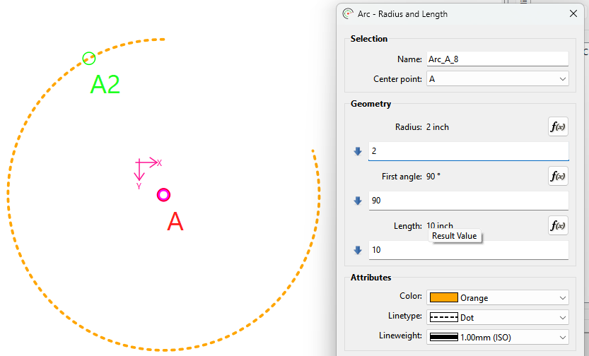
  1. In order to be able to set notches in arm and neck holes at predetermined intervals, and to make this visually easier for me, I simply described arcs (‘Arc - Radius and Length’) with circumference of the object in question. (Images: #1. #2 & #3)
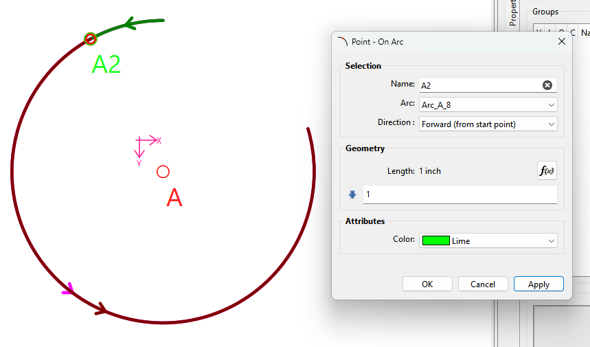
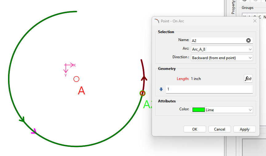
  2. The notch point, I represented with a ‘Point on Arc’ which I set using the circumference divided by the number of notches I need. (Images: #4, #5)

At this point I found I could not understand what is / are the determinations for :

  1. Starting point of the arc length,
  2. the direction in which the point ,offset calculated in the formula, is placed on the curve,
  3. What happens when the offset calculation should (even if unintentionally) be negative or exceed the value of the length if the arc length.
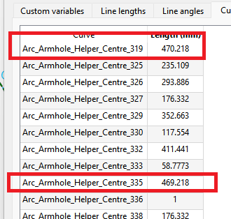
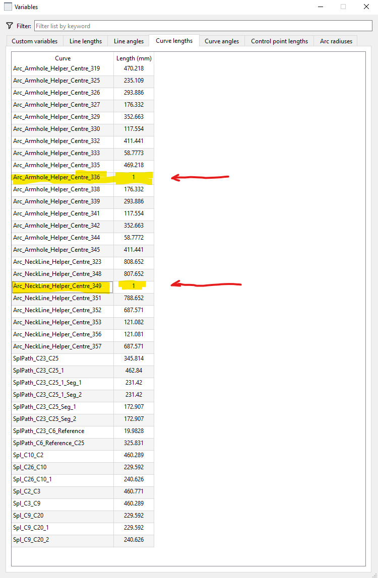
  4. Having - seemingly - created ‘nonsense’ points on the arc and deleted these there still seem to be remnants of these in the tables (see highlighted lines in Image #6.) How might one (me!) remove these?

So, in a ‘nutshell’, I would like to understand - on a purely technical level:

  • How to set the starting point of an arc consistently
  • How to set my points in the desired direction - this is important to me right now!
  • How to handle calculations that exceed the bounds / constraints of an arc

***********************************************************

On a more philosophic, and separated from the technical detail plane: Should anyone be willing / able to suggest easier / better / alternative methods for this particular exercise. I would love to hear from you.

***********************************************************

Since it no longer seems to be possible to edit one’s posts, I will post ‘As Is’ for now. Additions will have to be added as ‘Replies’ later!

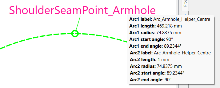
#1 Representation of (in this case) an arm hole :

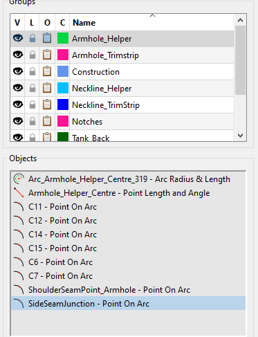
#2 ‘Groups’ representation of the arm hole :
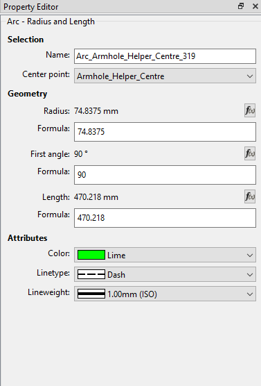
#3’ Draft Block ‘Properties’ :

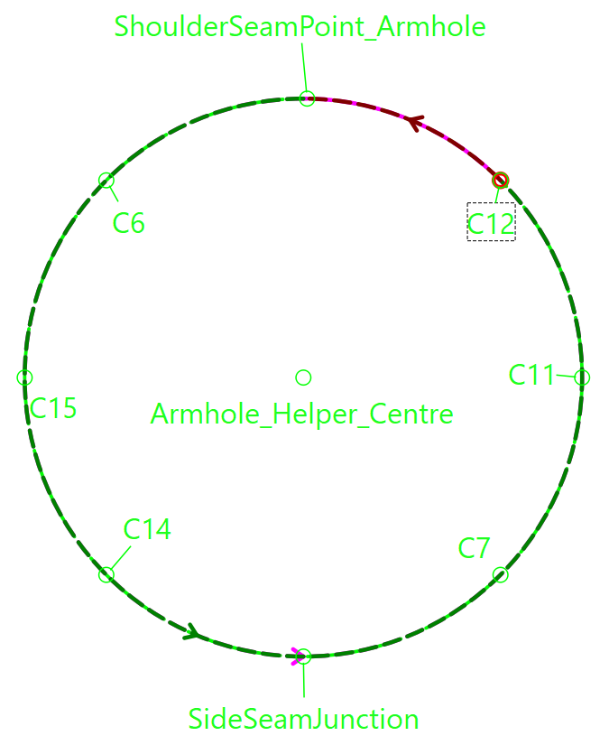
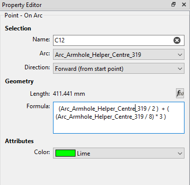
‘Properties’ of a ‘Point on Arc’ object :
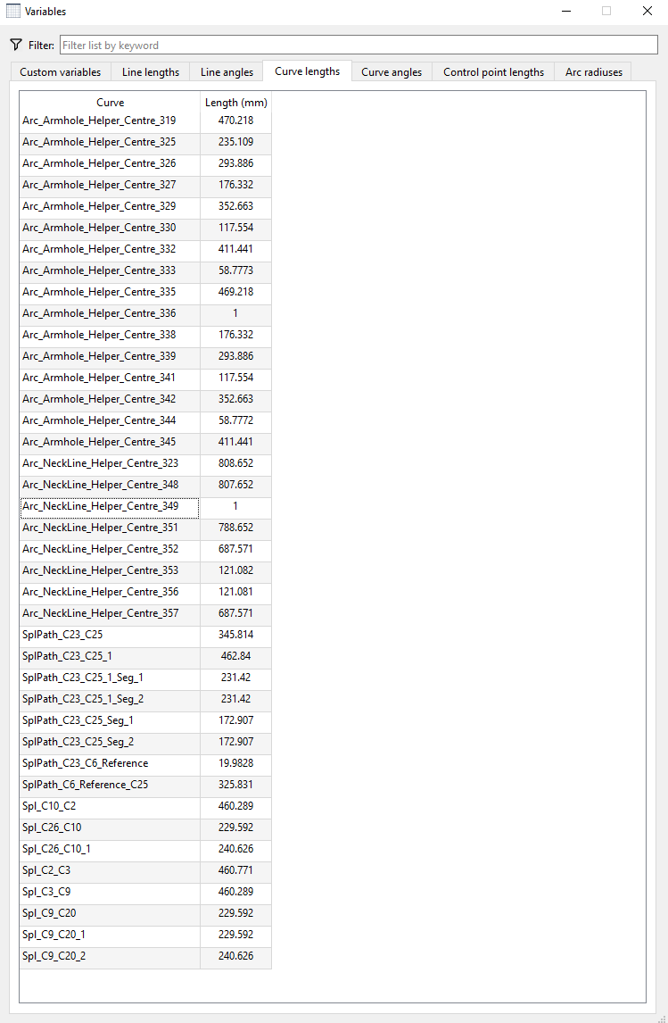
#5’ Here is the Variable Table, showing the curve lengths for the object in question:

#6 Here is the image displaying the the entries for the ‘nonsense’ points set, and subsequently removed - however the original offset data still seems to exist!

Thank you to everyone having the patience and stamina to have reached this point in my saga!

I greatly appreciate your help and suggestions in the above matters.

2 Mi Piace

Try the 3 dots…

2 Mi Piace

The Start point is at the First angle:

Here the Point on Arc A2 is 2" from the start of the arc which is at 90 deg.

Forward is Couterclockwise, Backward is Clockwise:

If going Forward the point is counterclockwise “from the start point”

If going backward the point is clockwise “from the end point”.

Note.. Arcs always go counterclockwise. I don’t know how difficult it would be to have the arows for a Backwards direction go Clockwise… which may help to indicate where it’s being measured from.

Unlike many of the line tools… The point is constrained to the arc segment, and is placed at the start or end point of the arc depending on direction and / or sign. Technically we probably should have two tools… Point on Arc, and Point on Arc Segment.

I have no answer. I can’t reproduce any error of NOT removing a Point on Arc. :thinking: I would need more info… such as the pattern.

3 Mi Piace

Starting with this one… As @Douglas said, we’ll need to see the pattern to determine why those points don’t want to be deleted and then we’ll be able to tell you. It could be that they are used to place the other points.

1 Mi Piace

There’s also the question of whether any “undo’s” were applied? Which may be leaving modeling nodes still in the pattern? I don’t know what the sequence of events that lead from start of the draft to screencap #6. So I can’t say if there is a bug or just a misunderstanding of the behaviour of the tool.

2 Mi Piace

Before you can do these accurately & consistantly, you need to understand arcs.

When you use splines, “all roads lead to Rome”. By this, I mean that you are joining lines and points with a curve, which coud be arc shaped.

When you use arcs, “Rome leads to all roads”. By this, I mean that you 1st have your arc anchored to a centre point and then you add your points and lines to your arc.

Things like armholes and necklines shift around according to measurements and designs, so you may end up with an arc sitting around the bellybutton instead of the Adam’s Apple :grin:, while a carefully constructed curve will always be in place - even if it looks like an arc.

So… it’s a case of “Choose your poison carefully!”

1 Mi Piace

Points are a dot. It has no direction. You can only change the label name to tell you which one gets selected 1st, 2nd or 3rd when creating the pattern piece.

Normally, you would mirror the curve/arc beyond the bounds of the existing one and then add points to the mirrored part.

However, if you give us a bit more detail about what you are trying to achieve, perhaps we can help you with a better solution.

1 Mi Piace

duh! …. :roll_eyes: :roll_eyes: :roll_eyes: :roll_eyes:

2 Mi Piace

I deleted the points, they are no longer presernt, only the seeminly persistant data.

2 Mi Piace

Hi Grace,

I humbly beg to differ on this, by setting - at that time appropriate values - I can set a point at various positions, either to the right or the left of the ‘origin’ of the arc … at least that is how it appears to me. Hence the desire / need to know the answers to the queries as posed.

As I say, this is purely the meed to understand how the points are set with reference to the origin fro the technical / mathematical / geometrical aspect. The design aspect should be initially disregarded.

2 Mi Piace

Hi Douglas,

That is a good question, I will have to see if any of my backed up versions can shed light on this.

Referring to your first posting, the presence of the ‘left over’ data is not causing any grief, but I wished only to find out what this was caused by, I hate ‘untidy’ tables and unaccountable data.

Pattern attached …

202604171810_TT_001_00.sm2d (35.4 KB)

2 Mi Piace

I think he meant which direction (as per the direction attibute) along the arc is the point placed or whether the length is plus or or minus… as I pointed out above.

3 Mi Piace

Hi (again) Grace

The desired goal is to understand the math / geometry of the placing of points. I wish not (initially) to get into design philosophy at this juncture - only understand whet the software is doing, and how (with which data) this is executed.

202604171810_TT_001_00.sm2d (35.4 KB)

2 Mi Piace

Or just use the Arc - Radius and Angle, and make a full circle. Being aware that a Point on Arc will still be constrained within the start and end points and will not wrap around.

2 Mi Piace

Answered. The “direction"attribute” will determine whether it’s using the start or end point as the “origin” , and whether you’re are going CW or CCW. Of course a negative value then reverses this. BTW… the direction attribute also applies to any other type of curve… it has to, as the Point on → direction attribute is a member of the abstractcurve class which is the base class for all arc & curve classes. Of course there is the exception of the Eliptical arc as we can’t place a point on one… yet. If I recall it’s going to take some calculus to be able to calculate .

2 Mi Piace

This is NOT an offset… this is one of the segment lengths created from cutting the arc with the Point on Arc tool. The point on arc creates 2 arc segments… one for the length of the Point on Arc length… and one for the length of the arc - the length of the Point on Arc.

470.218 - 469.218… drum roll… = 1.

It should be noted that with Arcs you can NOT place a point on the start or end point (0 length)… if you do it will automatically be placed 1mm away. So even though the length of the Arc = 470.218 and the length used in the Point on Arc = 470.218… it’s really 469.218… resulting in the arc segment length of 1mm. (Currently) This is because the routine that “cuts” the arc has to create 2 segments of positive length.

Also notice how the angle gets thrown off by the 1mm… instead 90 we get 89.2344. :roll_eyes:

Also would it make more sense if the varible names for the segments were more sensible… yes. Did I come up with the naming scheme… no. :roll_eyes:

4 Mi Piace

Thanks Douglas,

As I recall, you gave me this, or similar information, in regards to a query of mine regarding discrepancies in the placement of points on curves / arcs, these I thought at the time to indicate a software issue. I had not connected this to the current situation, although the effects are similar.

2 Mi Piace

@Grace and @Douglas

Thanks to you both for your patience :innocent: and willingness to accommodate this somewhat persistently obstinate pedant :roll_eyes: .

I’m still not quite out of the ‘woods’ yet, but with your able assistance, I’m sure to get there … :hugs:

2 Mi Piace

Depends on one’s point of view… currently the 1mm distance is a behavior RT built into the cut tools. Some may view not being allowed a 0 seg length as a software issue. I just accept it for the momment - as I do many previous choices made - as a low priority issue which I can change when I better understand that section of code without going down rabbit holes. :slight_smile:

2 Mi Piace

A very wise - from a programmer’s POV - choice!

2 Mi Piace