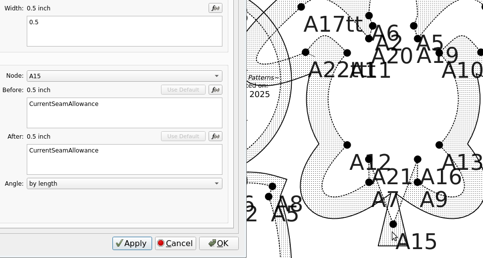
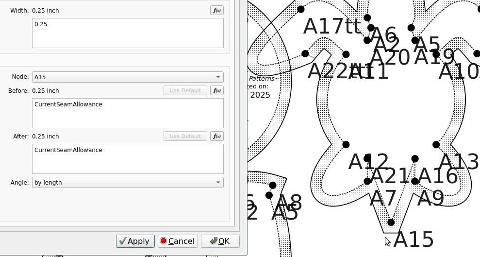
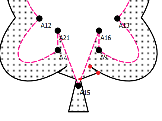
As you can see, the seam allowance cuts into the seamline at the tail. However, when I changed it to the quarter inch allowance I wanted for this pattern, it works fine:
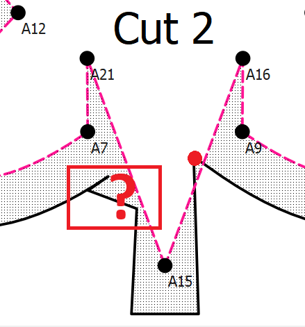
I’m sure it’s related to a real numbers / fuzzy math issue where the routine(s) that are establishing projected corner points of the seam allowance are not finding a correct intersection. This is kind of a weird edge case with the curve going into A7, to A21 to A15 to A16 to A9 to a curve… where the SA wants to follow the path and project the points at A7 and A9 and A21 and A16. Thing is all those points are meaningless in this case as the intersections actually happen at the curves intersecting Line_A21_A15 and Line_A16_A15. No doubt the fill between the mainpath (seamline) graphic item and the seam allowance (cutline) graphic item is also coming into play. It’s a case where as humans with eyes we can easily see how to adjust and draw the SA, but it’s hard to describe in code that “in this case” do this.
I’ll take a quick look at the pattern, but I don’t want to jump into another rabbit hole at the momment to fix this issue - as I’m trying to concentrate on developing the Marker feature.
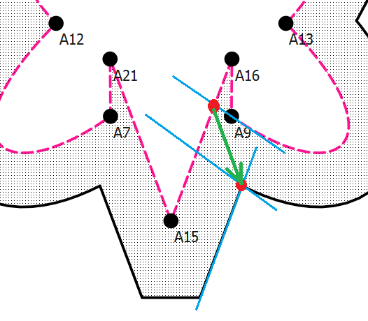
The red dot is correctly projected from point A9, but again is meaningless in this context. The other (3?) points I have no clue how they were calculated as I would have expected for A7 to be symmetrical to A9 like your original pic.
BTW… it seems that once the SA points for A7 and A9 cut into the mainpath, that’s when the SA error(s) show(s) up. Cutoff seems like anything above 0.28401 puts it inside the piece.
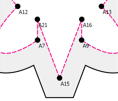
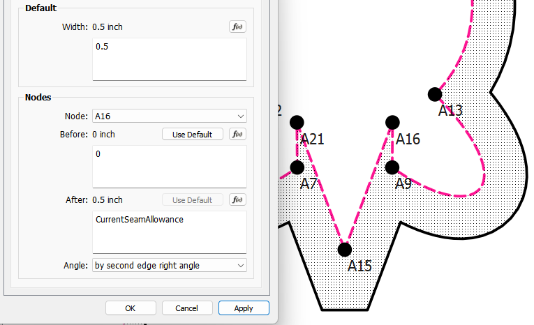
I was able to get a 1/2" SA by setting the SA along A9_A16 and A21_A7 to zero.
I’ll answer that… the corner type was set differently for A7 than was A9… with A9 set at 2nd edge symmetry and A7 at 1st edge symmetry it does the same on both sides:
Still not sure why it appears to be producing 3 points at the A7 and A9 corners? A corner is either 1 point (byLength) or 2 points (by any other type)… unless one of those is the A16 & A21 points?
Also changing the corner type for A21 or A16 has no effect at all. Which makes sense as an inside corner can only produce 1 point. I think the corner type defaults to byLength once the angle > 180. This might be something I’ll look at when I update the corner types, where types that don’t apply would be disabled in the dialog.
Playing around even further I found that just reducing the SA after value of A9 or the SB before value of A16 and vice versa for the other side also removes the errors.
Again, it’s easy for us to look at the whole piece and just remove A16 and A21 from the pictue and treat the SA as if A9 and A7 extend to the lines from A15.
The SA routines don’t look at it that way. They only look at the SA corners sequentially one node point at a time and can’t take into account prev or next SA nodes.The app is just calculating projected points and playing connect the dots while we can just remove dots that don’t make sense. Even given all the AI power in the world, sometimes the human brain can just know that something is not correct - even not having ever seen it before.
Thanks for taking a look! I definitely agree that even if it’s something that can be fixed in the back end, the Marker takes precedence! I hadn’t thought of setting the blind corner to 0 SA & hope I will remember next time something like this comes up.