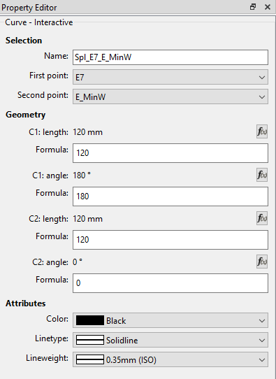
is it possible to adjust control point lengths per formula?
I have checked to see if I could set a series of control points - using the following two control point lengths (C1 Length & C2: Length) as examples - to adjust their lengths per formula, relative to each other.
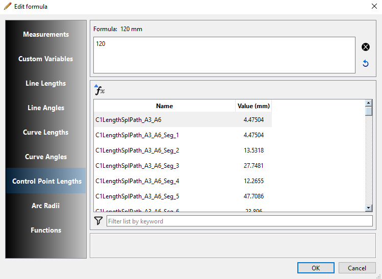
The presence of a formula group “Control Point Lengths“ led me to believe that this should be possible, however I do not see any positions in the list that would relate to the curves / splines that I need to reference.
Is this indeed possible, or are these values listed in the selection box (Edit Formula) not related to the actual lengths (Property Editor) that I would like to link / relate to other objects of the same type?
I welcome any advice or corrections to my assumptions. Thanks.
Seamly Rule # 1… everything is linear in the pattern. Tools can only see what tools and variables came before it.
If you click the fx button in a tool, and look up CP lengths, you can only see the CP lengths of splines created before the tool you are editing. The tool can not see CP lengths for splines created after it. Think of it as reading a book. If you read up to page 100, you only know about the characters extablished on pages 1-100… you don’t know about any new characters you have not read about yet.
That’s why the Formula Editor is there. It forces you to use only valid variables for THAT tool in the formulas. The Variables table on the other hand is an overview of all the variables, but every tool does not have access to every variable.
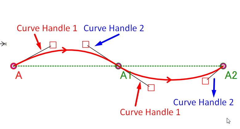
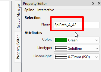
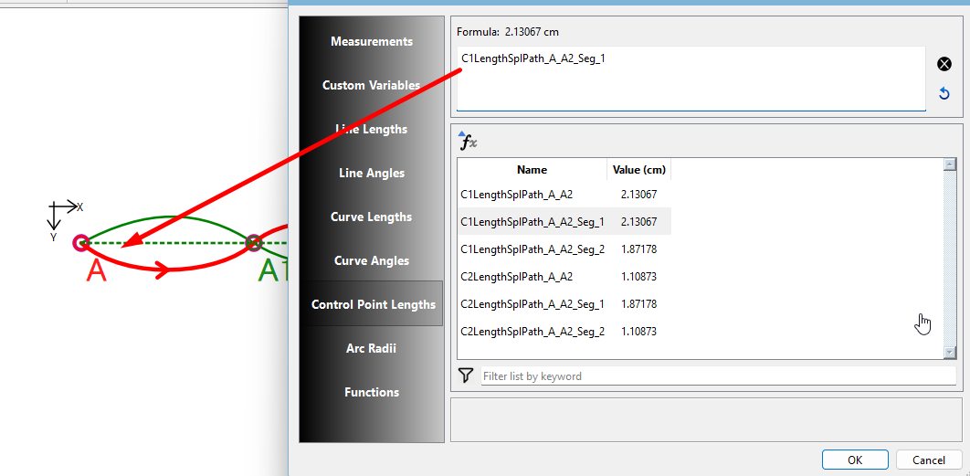
Yes, those are the control handle lengths that I would use in a formula. The C1 in front of the spline name means Control Handle 1. If you scroll down a bit, you’ll find the same with a C2 in front. These are the 2nd Control Handles.
The trailing _Seg_1 is the first segment of the spline, _Seg_2 is the second segment, etc. etc. As far as I can see, this spline has 6 or more segments, so you really do need to count which segment you want to reference.
Unfortunately there’s not really a better way to notate the segments other than making the name ridiculously longer by adding the segment starting and ending point names.
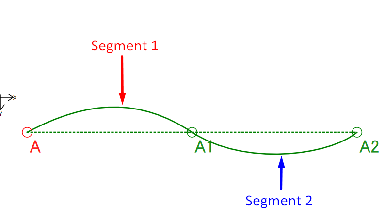
I’m wondering if we could add 2 new columns to the table that displays the Start and End point names? That way the variable name can stay the same, but you would be able to identify which points a segment is between? The same issue exists when you have multiple Points on a curve, where it can be difficult to figure out which “segment” you want.
Why not?.. segment one is between A and A1… segment 2 is between A1 and A2.
C1LengthSplPath_A_A2_seg1 and C2LengthSplPath_A_A2_seg1 are between A and A1.
C1LengthSplPath_A_A2_seg2 and C2LengthSplPath_A_A2_seg2 are between A1 and A2.
Name                         Value    Seg Start Pt   Seg End point
C1LengthSplPath_A_A2_seg1     5.0           A             A1
C1LengthSplPath_A_A2_seg2     4.0           A1            A2
C2LengthSplPath_A_A2_seg1     5.0           A             A1
C2LengthSplPath_A_A2_seg2     4.0           A1            A2
And of course if the curve is CCW:
C1LengthSplPath_A2_A_seg2 and C2LengthSplPath_A2_A_seg2 are between A1 and A.
C1LengthSplPath_A2_A_seg1 and C2LengthSplPath_A2_A_seg1 are between A1 and A2.
Don’t feel bad. I just experieced the same sort of thing the other night working on the History dialog trying to insert a tool and kept getting an id error. I thought what the hell did I break now? After umpteen crashes I realized I was trying to insert a tool by row number and not the tool name. Duh.