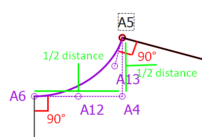
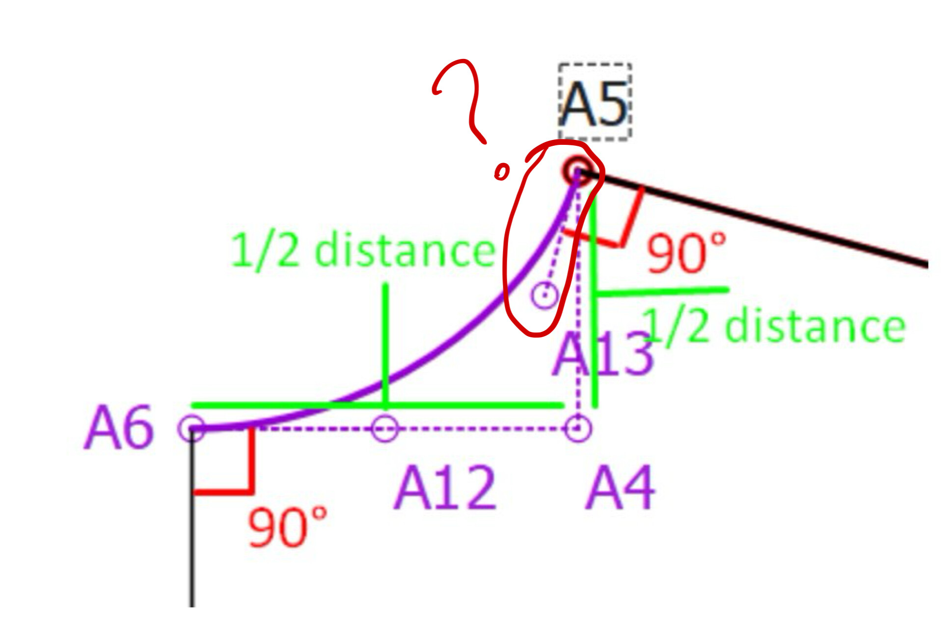
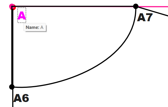
A12 & A13 are the control handle points which may be adjusted later to fine-tune your curve according to what you want.
The curve handles need to be at 90° to a straight seam or fabric fold, otherwise it will form a peak and not a smooth curve when sewn. A perfect circle (in a square) is slightly more than 1/2 distance of the side of a square, but you may play with the distances to see what happens when you lengthen or shorten the curve handle point.
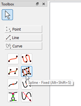
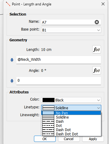
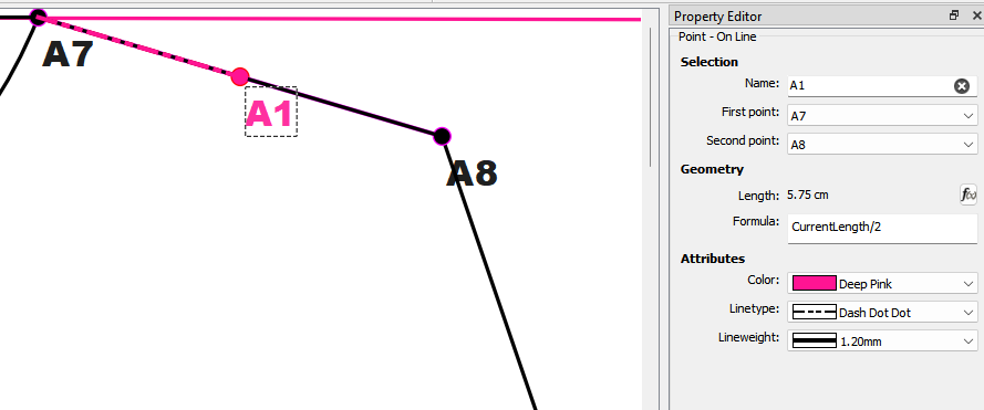
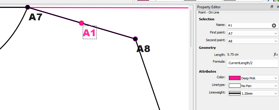
He uses the No Pen line type, this way, only the point shows and not the line connecting it.
He uses the Fixed Spline tool to create the curve after he has place all the points:
The points that are not passed through are control handle points. Once you have selected the tool, you click on the start point, then the 1st control handle (CH) point, the 2nd control handle point and then the 1st point to pass through, then the 3rd CH point, the 4th CH point, the 2nd point to pass through, etc. etc. until you have completed the curve and end on the last point. Each point that gets passed through should have 2 CH points between it and the previous or the next point.
The 1st CH point is the control handle for the preceding point and the 2nd CH point is the control handle for the next point.
Question 1.2) “A12 & A13 are the control handle points which may be…”
I don’t know If you talk about just for the T-Shirt Neckline specifically.
I did not give this example for just the Neckline of a T-Shirt.
It is a general question to control, present and draw any curvitures in general.
Side seam of Trousers
Neckline of a dress
Side seam of a dress
Etc.
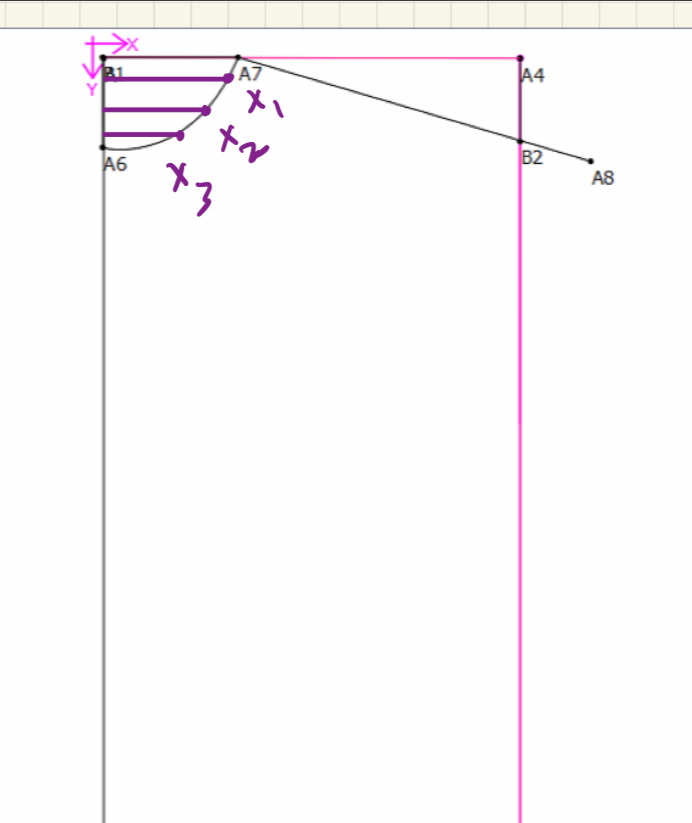
With guide lines I presented even you can transfer your pattern drawn on a muslin paper to Seamly2D.
Maybe It can be thought as a Pattern Making technique rather than Seamly Method but we also need to this technique to draw a curve similar to a pattern drawn on a muslin paper.
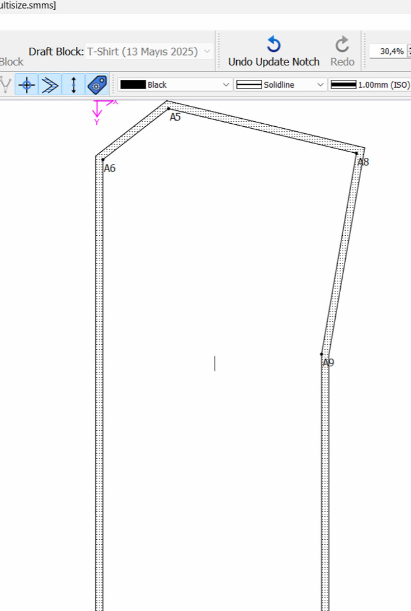
Question 1.3) Do you need the Control Handle line which is perpendicular to the shoulder line. (I presented It with a red question mark)
Because It looks like you did not use this line and the angle while drawing a perpendicular line to the line with the points A6, A12, A4.
???
Question 2.2) “No Pen Line Type”
I could not find this Tool at the Line Tools Section.
Question 6) What are the difference between these two tools?
A) Spline - Fixed : You click the Control Handle Points and It draws automatically right?
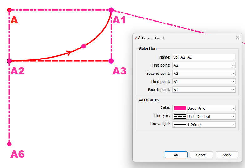
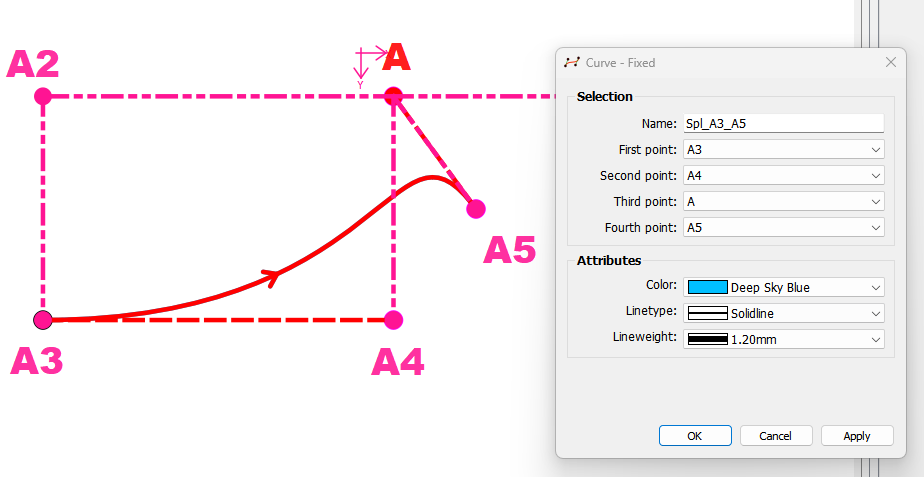
B) Curve - Fixed : you specify up to 4 Guide Points and It draws automatically right?
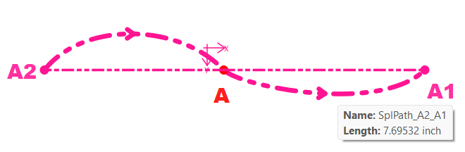
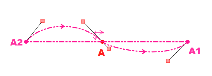
Now there are 2 types of Curves and Splines. Interactive and Fixed.
Interactive is where you can move the control points Interactively, thus setting the length and angle. In an interactive curve or spline it will display the square control handles (if toggled on):
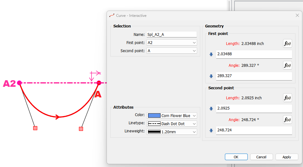
Fixed Curves and Splines are where the control points are fixed to some other points in a draft block. They can not be moved. For example In this Fixed curve the Start point is A3, the Endpoint is A… the control points are A4 and A.
The Fixed Splines are just like Fixed Curves where again you’re just drafting a curve between more than 2 points, but in this case with fixed control points in between.
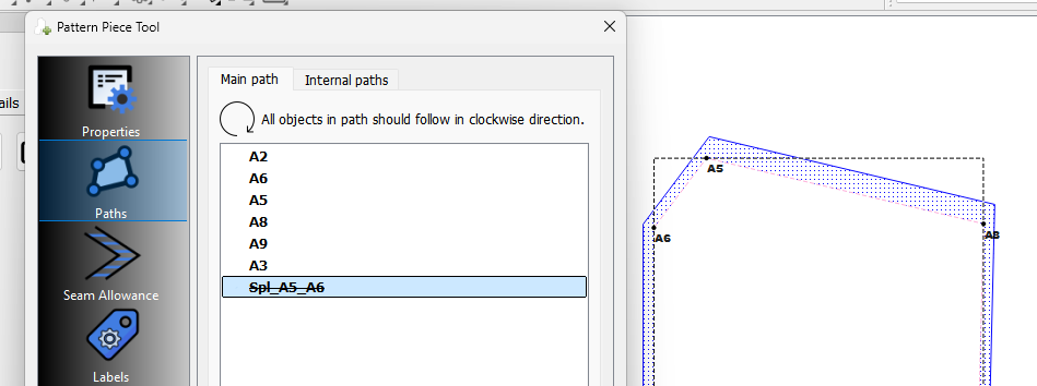
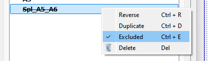
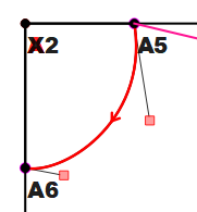
Basically a curve is a close-enough-to-infinite series of points on a curved path. In order to trace the points of the curve, click on the curve. If the arrow on the curve is pointing against the trace direction, hold shift while clicking on it, or manually select “reverse” in the piece properties dialog.
Already been answered in the other topic on adding a notch.
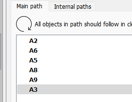
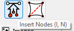
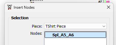
Because you have not added the curve as you were tracing… also pointed out in another topic. At this point you need to insert the curve using the Insert Nodes tool - also pointed out in another topic.
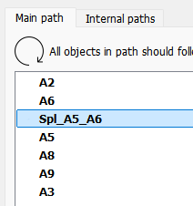
Note: You can also hold the Shift key as you select a curve while adding with the Add Piece or Insert Nodes tools or use the context menu in the path list: